Mechanism for gear shifting and stroke detection of gearbox

A technology for stroke detection and gearbox, which is applied in the direction of machine gear/transmission mechanism testing, measuring devices, instruments, etc. It can solve the problems of unable to find the production rhythm, low test run efficiency, and unqualified conditions, so as to improve the efficiency of gear shifting and detection , reduce the rate of returning to the factory, and improve the effect of the qualified rate

Inactive Publication Date: 2015-05-06
HANGZHOU ADVANCE GEARBOX GRP
View PDF7 Cites 3 Cited by
  • Summary
  • Abstract
  • Description
  • Claims
  • Application Information

AI Technical Summary

Problems solved by technology

[0004] aTurning the shift handle after the motor starts may cause the handle to fall off and fall onto the rotating flange, which may easily cause personal injury
The proximity of the shift handle to the output flange also presents potential safety hazards
[0005] b. The shifting force of each gear is up to 350-400N. It is difficult to directly push and pull to shift gears and cause hand discomfort.
[0006] c. The shifting stroke accuracy of each gear reaches 11±0.1mm. After the first gear is engaged, there is interference between the shift fork and the box, which leads to the phenomenon that the gear is not in place, such as image 3 The position shown is impossible to detect visually and the existing production rhythm does not meet the conditions for each machine to detect a stroke.
[0007] Difficult to engage in the D gear and the sampling inspection process of the shift stroke makes the overall test run efficiency low

Method used


Image

  • Mechanism for gear shifting and stroke detection of gearbox
  • Mechanism for gear shifting and stroke detection of gearbox
  • Mechanism for gear shifting and stroke detection of gearbox

Examples


Embodiment

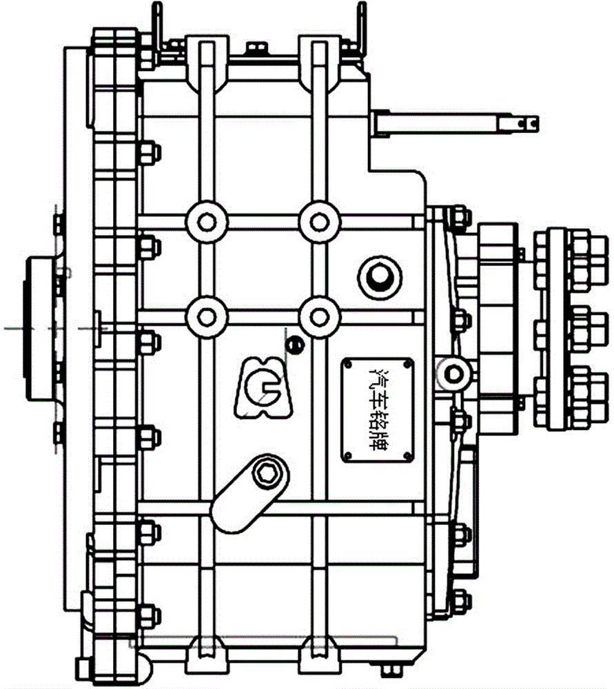
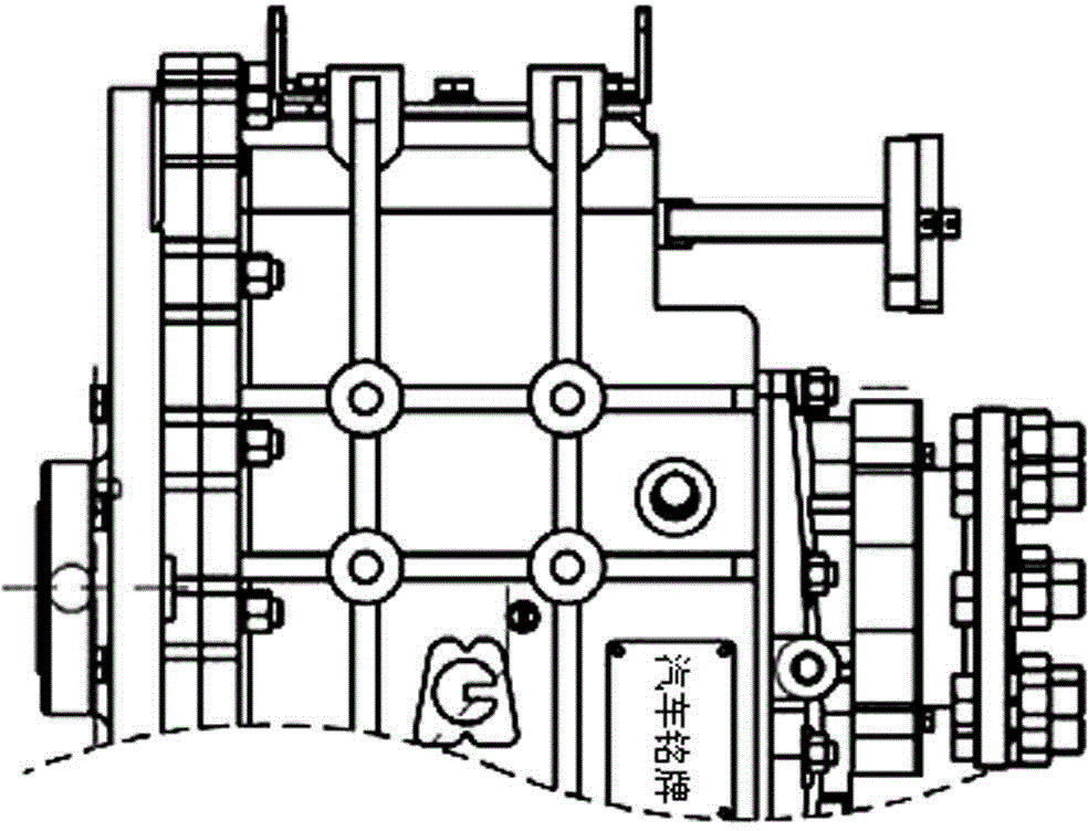
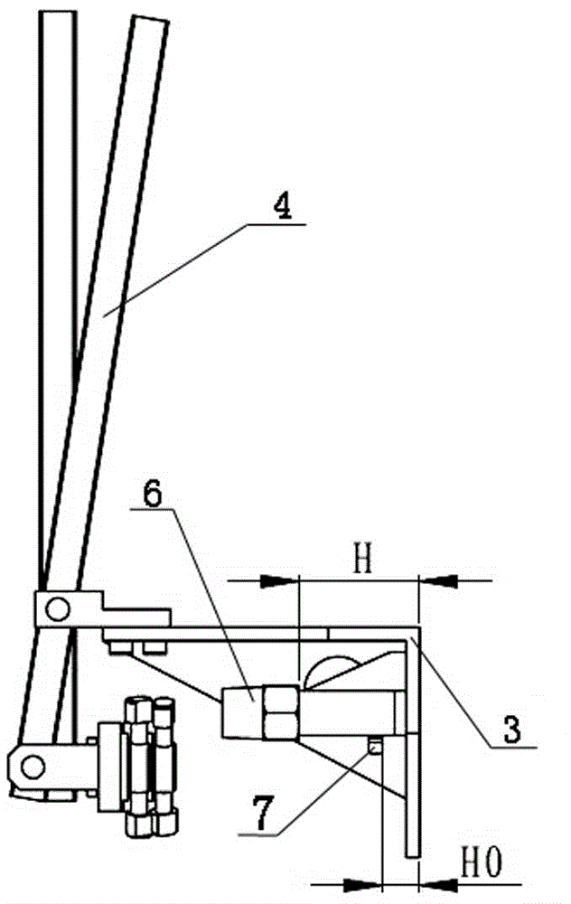
[0023] Embodiment: The present invention can also be called a kind of tooling, which is composed of tooling main body and stroke detection. The shifting wheelbase of the tooling body is determined by the gearing wheelbase of the gearbox. The position of the shifting lever is designed so that The shift lever is vertical in the neutral position. The fixing holes of the main body of the tooling correspond to the positions of the threaded holes of the box body. The rotating body part A on the tooling adopts a half-hole and half-thread design, which can make it play a guiding role when combined with the shift shaft, and facilitate the screwing of the threads. A certain ratio is selected at both ends of the fulcrum of the shift lever to reduce the shifting force. The light hole of the fixed rotating sleeve B on the shift lever is designed with a long slot to offset the dimensional change along the direction of the lever when shifting gears. The distance H between the plane of the si...


PUM


Abstract

Disclosed is a mechanism for gear shifting and stroke detection of a gearbox. The mechanism mainly comprises a gear shifting body and a stroke detection assembly. The gear shifting body comprises an L-shaped support, wherein the L-shaped support is fixedly installed on a box body side wall, a gear shifting shaft stretches out of the box body side wall, a gear shifting lever is hinged to the outer end of the L-shaped support, and the lower end of the gear shifting lever is connected to the gear shifting shaft through a hinged connecting rod. The stroke detection assembly comprises a base, wherein the base is installed on the box body side wall on the side of the gear shifting shaft, a signal lamp switch is installed outside the base, and a trigger rod is allocated. The L-shaped support is fixed on the box body side wall through a bolt, the connecting rod is connected with the gear shifting shaft through a rotating body component, and a rotating sleeve is fixed to the connecting rod; the distance H between the plane of the signal lamp switch installed on the base of the stroke detection assembly and the box body side wall with the L-shaped support is obtained from the negative allowance. The mechanism has the advantages of being simple in structure and convenient to use and operate, reducing the accident risk and the labor intensity, increasing the product percent of pass, and improving the working efficiency.

Description

technical field [0001] The invention relates to a mechanism for gear shifting and stroke detection of a transmission, and belongs to the technical field of transmission testing. Background technique [0002] The shift shaft of EMT electric transmission is mostly a parallel shift shift structure, and its outline is as follows figure 1 As shown, when shifting, it is required to push two shift shafts in turn to drive the shift fork to hang each gear for a test run, and the shift stroke of each gear must reach 11±0.1mm. The existing test gear shifting method is to screw the two handles into the thread of the corresponding shift shaft end, such as figure 2 As shown, after the motor is started, the push-pull handle is hung into the fourth, third, second, and first gears successively to realize the gear shifting operation. Because the shifting force of each gear of this gearbox reaches 350-400N and there is no synchronizer structure, there will be frustration and difficulty...

Claims


Application Information

Patent Timeline
IPC IPC(8): G01M13/02G01B21/02
Inventor 张凯
Owner HANGZHOU ADVANCE GEARBOX GRP
Why Eureka
Try Eureka