
Television core test circuit and system

A technology for testing circuits and TV sets, applied in the field of TV, can solve the problem of high difficulty of testing

Inactive Publication Date: 2015-04-08
SHENZHEN SKYWORTH RGB ELECTRONICS CO LTD
View PDF5 Cites 8 Cited by
  • Summary
  • Abstract
  • Description
  • Claims
  • Application Information

AI Technical Summary

Problems solved by technology

Since each device needs to be debugged, the test is more difficult

Method used


Image

  • Television core test circuit and system
  • Television core test circuit and system
  • Television core test circuit and system

Examples


Embodiment Construction

[0027] It should be understood that the specific embodiments described here are only used to explain the present invention, not to limit the present invention.

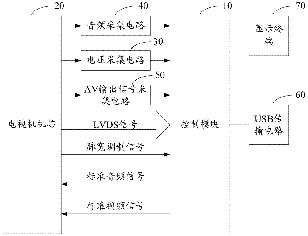
[0028] The invention provides a TV core test circuit, referring to figure 1 , in one embodiment, the TV core test circuit includes:

[0029] The control module 10 is used to output standard audio signals and standard video signals to the TV core 20, and collect the LVDS (Low Voltage Differential Signaling) signal output by the TV core 20;

[0030] A voltage acquisition circuit 30, configured to acquire a voltage value at a preset position in the main board of the TV set, and output the voltage value to the control module 10;

[0031] An audio collection circuit 40, configured to collect the audio playback signal output by the TV core 20, and output the audio playback signal to the control module 10;

[0032] The control module 10 compares the LVDS signal with the standard video signal, compares the audio playback si...


PUM


Abstract

The invention discloses a television core test circuit. The television core test circuit comprises a control module, a voltage acqusition circuit and an audio acqusition module, wherein the control module is used for outputting a standard audio signal and a standard video signal to a television core and acquiring an LVDS (Low Voltage Differential Signaling) signal output by the television core; the voltage acqusition circuit is used for acquiring a voltage value of a preset position of a television motherboard and outputting the voltage value to the control module; the audio acqusition module is used for acquiring an audio play signal output by the television core and outputting the audio play signal to the control module; the control module is used for comparing the LVDS signal with the standard video signal, comparing the audio play signal with the standard audio signal and comparing the voltage value with the preset standard voltage; thus the test of the television core is realized. The invention also discloses a television core test system. The test difficulty of the television core is reduced.

Description

technical field [0001] The invention relates to the field of television technology, in particular to a television core testing circuit and system. Background technique [0002] At present, when testing the core of a TV, usually multiple signal generators are used to connect to the main board of the TV, and then the existing testing instruments are used for data collection, and the collected data is used to cooperate with the industrial computer for data processing to complete the test. Testing of TV chips. Since each device needs to be debugged, the test is more difficult. [0003] The above content is only used to assist in understanding the technical solution of the present invention, and does not mean that the above content is admitted as prior art. Contents of the invention [0004] The main purpose of the present invention is to provide a TV core testing circuit and system, aiming at reducing the difficulty of testing the TV core. [0005] In order to achieve the a...

Claims


Application Information

Patent Timeline
Patent Type & Authority Applications(China)
IPC IPC(8): H04N17/04
Inventor 方威侯亚荣
Owner SHENZHEN SKYWORTH RGB ELECTRONICS CO LTD
Learn More