
A chip mounting structure and a connector using the same

A chip installation and connector technology, applied in the direction of connection, parts of the connection device, contact parts, etc., can solve the problems of poor contact of the chip and inability to take out the chip conveniently, and achieve the effect of easy replacement

Active Publication Date: 2017-01-11
CHINA AVIATION OPTICAL-ELECTRICAL TECH CO LTD
View PDF12 Cites 2 Cited by
  • Summary
  • Abstract
  • Description
  • Claims
  • Application Information

AI Technical Summary

Problems solved by technology

[0003] The purpose of the present invention is to provide a chip mounting structure, which solves the technical problem of poor contact caused by the weak connection of the chip in the prior art, and the technical problem that the chip cannot be taken out conveniently when the chip is replaced. At the same time, the present invention The invention also provides an optical fiber connector using the chip mounting structure

Method used


Image

  • A chip mounting structure and a connector using the same
  • A chip mounting structure and a connector using the same

Examples


Embodiment Construction

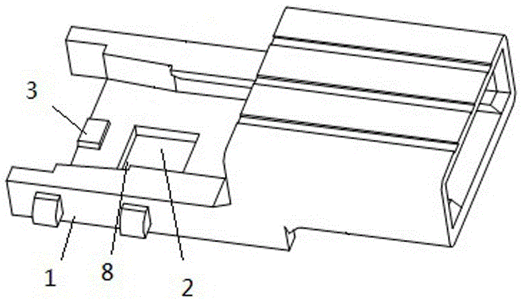
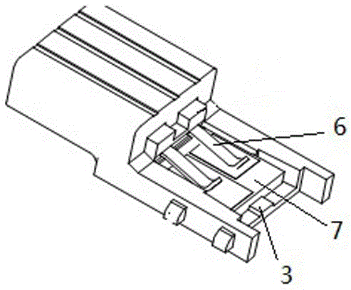
[0015] An embodiment of a chip mounting structure, such as Figure 1-2 As shown: the chip mounting structure in this embodiment includes a mounting base 1 and a chip 7. The mounting base is provided with a mating surface for matching and supporting the position of the bottom surface of the chip. Move along the direction parallel to the mating surface and break away from the blocking structure of the mating surface, the thickness of the blocking structure extends along the direction perpendicular to the mating surface, and the mounting seat is provided with a device for applying a pressing force to the chip toward the mating surface Elastic pressing piece 6, the lower surface of the mounting seat is provided with an unlocking operation port, and the unlocking operation port provides an entrance for the force application object used to push the bottom surface of the chip away from the mating surface, and the mating surface is provided with the unlocking operation port. The unloa...


PUM


Abstract

The invention discloses a chip mounting structure and a connector with the chip mounting structure. The chip mounting structure comprises a mounting seat and a chip, wherein the mounting seat is provided with a matching surface which corresponds to the bottom surface of the chip and is in support matching with the bottom surface of the chip, the mounting seat is provided with a retaining structure around the matching surface, the retaining structure can prevent the chip from moving along the direction parallel with the matching surface and disengaging from the matching surface, the thickness of the retaining structure extends along the direction vertical to the matching surface, the mounting seat is provided with an elastic press sheet which is used for applying pressing force on the chip, an unlocking operation opening is arranged at the surface of the mounting seat, and is used for providing an inlet for pushing the bottom surface of the chip to disengage from an force applying object of the matching surface, the matching surface is provided with a charging and discharging opening which is communicated with the unlocking operation opening through a passage, and the charging and discharging opening is used for providing an outlet for the force applying object to extend out and continuously push the chip so as to overcome the limitation of the elastic force of the elastic press sheet disengaging from the retaining structure. The chip mounting structure has the advantages that the reliable installation of the chip is effectively guaranteed, and the replacement of the chip is convenient.

Description

technical field [0001] The invention relates to the field of chip mounting, in particular to a chip mounting structure and a connector using the chip mounting structure. Background technique [0002] The Chinese patent No. 200810304328.7 discloses a chip mounting structure. The structure has a housing, including a mounting seat and a chip. The opening is pushed into the chip mounting position, and the chip can be fixed in the up and down direction by other components, but the chip is easy to come out from the opening on the mounting seat, which affects the normal use of the chip, and the chip needs to be replaced When using the push rod, the chip is pushed out from the mounting port of the mounting seat, but because the chip mounting position is too narrow, it is not easy to push it out from the mounting position, and the chip cannot be easily taken out when the chip is replaced. Contents of the invention [0003] The purpose of the present invention is to provide a chip ...

Claims


Application Information

Patent Timeline
Patent Type & Authority Patents(China)
IPC IPC(8): H01R13/24H01R13/46H01R13/639H01R13/633H01R12/71
CPCH01R12/71H01R13/24H01R13/46H01R13/629H01R13/633H01R13/639
Inventor 孙亚磊李小卫王金殿
Owner CHINA AVIATION OPTICAL-ELECTRICAL TECH CO LTD
Learn More