
Current transformer saturation recognition method for differential protection

A current transformer and differential protection technology, which is applied in the field of relay protection of power systems, can solve problems such as difficult to accurately set the percentage of harmonic content, large dispersion of derivative or differential calculation results, and inability to quickly open differential protection, etc., to achieve The effect of fast recognition speed, small calculation amount and strong anti-interference ability

Inactive Publication Date: 2015-03-25
UNIV OF JINAN
View PDF5 Cites 24 Cited by
  • Summary
  • Abstract
  • Description
  • Claims
  • Application Information

AI Technical Summary

Problems solved by technology

[0011] However, the above-mentioned technical solutions still cannot completely eliminate the impact of the transient saturation of the current transformer on the current differential protection, especially the following problems: it is difficult to distinguish the time difference method when it is seriously saturated; it is difficult to accurately set the percentage of harmonic content; the calculation result of derivative or difference Large discreteness, poor anti-interference ability; misjudgment of transitional faults as transient saturation, unable to quickly open differential protection, etc.

Method used


Image

  • Current transformer saturation recognition method for differential protection
  • Current transformer saturation recognition method for differential protection
  • Current transformer saturation recognition method for differential protection

Examples


Embodiment Construction

[0045] The embodiments of the present invention will be described in further detail below in conjunction with the accompanying drawings and examples, but not as a limitation to the scope of protection of the present invention, all technical solutions obtained by means of equivalent replacement or equivalent transformation are within the scope of protection of the present invention Inside.

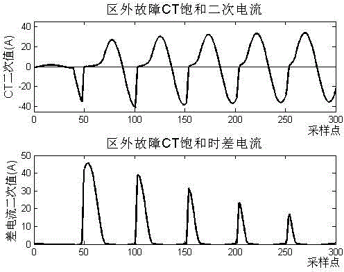
[0046] According to the method of the present invention, in the current differential protection device, the saturation identification process of the current transformer is carried out by using the half-cycle integral feature of the differential current sampling value as follows: figure 1 shown. figure 2 , image 3 They are the secondary current and differential current waveform diagrams of current transformer saturation for internal faults and external faults respectively. It can be seen that there are obvious distortions and defects in the differential current waveform after the current...


PUM


Abstract

The invention discloses a current transformer saturation recognition method based on the half-cycle integral characteristic of a differential current. The method is suitable for current differential protection of main equipment or power transmission lines. During an internal fault, a sliding data window half-cycle integral result of a differential current sampling value sequence is monotonically increased; when a current transformer is saturated during an external fault, the sliding data window half-cycle integral result of the differential current sampling value sequence has an obvious inflection point and is increased first and then decreased according to the variation tendency. According to the characteristic, after the fault is started, the variation tendency of the half-cycle integral value of the differential current is continuously judged in each fundamental wave cycle; once an obvious inflection point of the half-cycle integral value is found, the differential current is determined to be a false differential current caused by saturation of the current transformer; if no obvious inflection point of the half-cycle integral value is found, recognition and judgment are continuously carried out till saturation is determined, or the fault is removed and a complete protection device is reset. The recognition method is simple in logic, small in calculation amount and free of complex setting.

Description

technical field [0001] The invention belongs to the field of electric power system relay protection, and in particular relates to a current transformer saturation identification method suitable for current differential protection. Background technique [0002] The differential protection principle based on Kirchhoff's current law is simple, reliable, highly reliable, and has the advantages of absolute selectivity and no vibration effects, so it is widely used in generators, transformers, busbars and main power transmission lines. Protect. [0003] In the actual relay protection system, it is necessary to convert the large current of the primary system into a secondary current signal through a current transformer, and then apply the differential principle to the secondary current signal to realize the protection function. However, the transient saturation phenomenon of the electromagnetic current transformer itself will cause a huge unbalanced current in the differential cir...

Claims


Application Information

Patent Timeline
IPC IPC(8): H02H3/26
Inventor 刘益青高伟聪王成友
Owner UNIV OF JINAN
Learn More