Real vehicle in-loop simulation test method, real-time simulator and system
A real-time simulation and simulation test technology, applied in the automotive field, can solve the problems of low accuracy of performance test results and reduce the accuracy of performance test results of the controller under test, so as to reduce the risk of testing and enhance reproducibility , cost-saving effect
- Summary
- Abstract
- Description
- Claims
- Application Information
AI Technical Summary
Problems solved by technology
Method used
Image
Examples
Embodiment 1
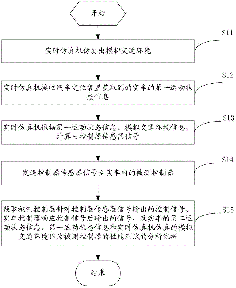
[0043] This embodiment shows the actual vehicle-in-the-loop simulation test method provided by the present application, which is used for performance testing of the controller under test. The controller under test involved in this embodiment is specifically a controller related to active safety, such as a driverless vehicle system, an automatic parking system, an automatic cruise system, a lane departure warning system, or a blind spot monitoring system.
[0044] In the real vehicle loop simulation test method provided by this application, the real vehicle, that is, the real vehicle, participates in the performance test of the controller under test, which ensures that the vehicle dynamics, road, driver, power, transmission and other systems of the vehicle are real. existing.
[0045] The real vehicle in-the-loop simulation test method provided by this application is based on the real vehicle HIL system installed in the real vehicle. The real vehicle HIL system includes a real-...
Embodiment 2
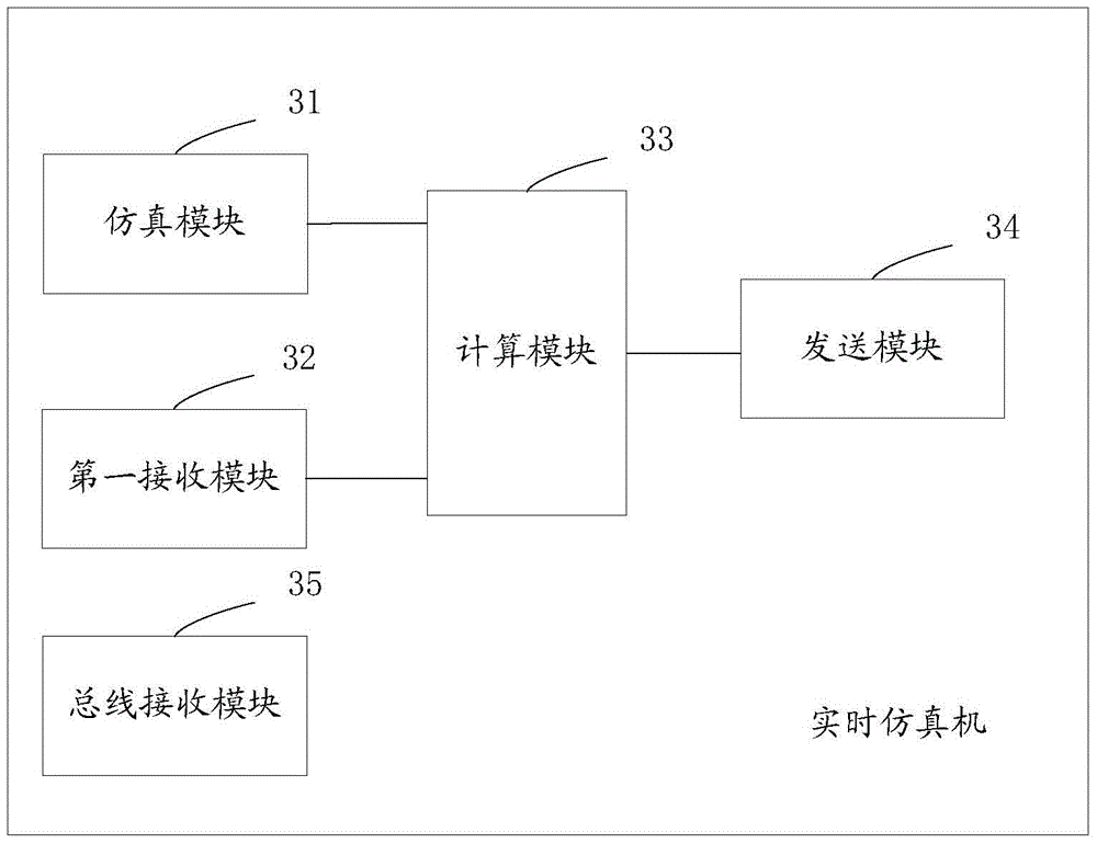
[0075] In this embodiment, a real-time simulator provided by this application is shown, please refer to image 3 , which shows a schematic diagram of a logical structure of the real-time simulator provided by the present application, the real-time simulator includes: a simulation module 31, a first receiving module 32, a computing module 33, a sending module 34 and a bus receiving module 35, wherein:
[0076] The simulation module 31 is used to simulate a simulated traffic environment.
[0077] The first receiving module 32 is configured to receive the first motion state information of the real vehicle acquired by the vehicle positioning device of the real vehicle HIL system to which the real-time simulator belongs.
[0078] A calculating module 33, configured to calculate controller sensor signals according to the first motion state information and the simulated traffic environment.
[0079] In this embodiment, the calculation module 33 may specifically include a first calcu...
Embodiment 3
[0087] In this embodiment, the actual vehicle HIL system provided by the application is shown, please refer to Figure 4 , shows that the HIL system includes: a vehicle positioning device 41 and a real-time simulator 42 .
[0088] For the specific structure and functions of the real-time simulator 42, please refer to Embodiment 2, and details will not be repeated here.
[0089] The vehicle positioning device 41 is connected with the real-time simulator 42, and is used to obtain the motion state information of the real vehicle
[0090] The vehicle positioning device 41 is specifically used to obtain the first motion state information and the second motion state information involved in Embodiment 1 and Embodiment 2.
[0091] Figure 5 The real vehicle HIL system shown can be powered by the power supply of the real vehicle. Of course, an independent power supply method can also be adopted. If the actual vehicle HIL system adopts an independent power supply mode, then Figure...
PUM
 Abstract
Description
Claims
Application Information
 - R&D
- Intellectual Property
- Life Sciences
- Materials
- Tech Scout
- Unparalleled Data Quality
- Higher Quality Content
- 60% Fewer Hallucinations
Browse by: Latest US Patents, China's latest patents, Technical Efficacy Thesaurus, Application Domain, Technology Topic, Popular Technical Reports.
© 2025 PatSnap. All rights reserved.Legal|Privacy policy|Modern Slavery Act Transparency Statement|Sitemap|About US| Contact US: help@patsnap.com


