
Stamping device

A technology of stamping equipment and punches, applied in the field of stamping equipment, can solve the problems of leaving wear marks on the surface of sheet metal parts

Inactive Publication Date: 2015-03-25
INVENTEC PUDONG TECH CORPOARTION +1
View PDF6 Cites 3 Cited by
  • Summary
  • Abstract
  • Description
  • Claims
  • Application Information

AI Technical Summary

Problems solved by technology

[0005] The invention relates to a stamping equipment, especially a stamping and bending mold of the stamping equipment, so as to solve the problem that the mold leaves wear marks on the surface of sheet metal parts

Method used


Image

  • Stamping device
  • Stamping device
  • Stamping device

Examples


Embodiment Construction

[0015] The present invention will be described in further detail below in conjunction with the accompanying drawings and specific embodiments. Advantages and features of the present invention will be apparent from the following description and claims. It should be noted that the drawings are all in a very simplified form and use imprecise ratios, which are only used to facilitate and clearly assist the purpose of illustrating the embodiments of the present invention.

[0016] The detailed features and advantages of the present invention are described in detail below in the specific embodiments, the content of which is sufficient to enable any person familiar with the relevant art to understand the technical content of the present invention and implement it accordingly, and according to the content disclosed in this specification, the claims and the drawings Any person skilled in the art can easily understand the related objects and advantages of the present invention. The fol...


PUM


Abstract

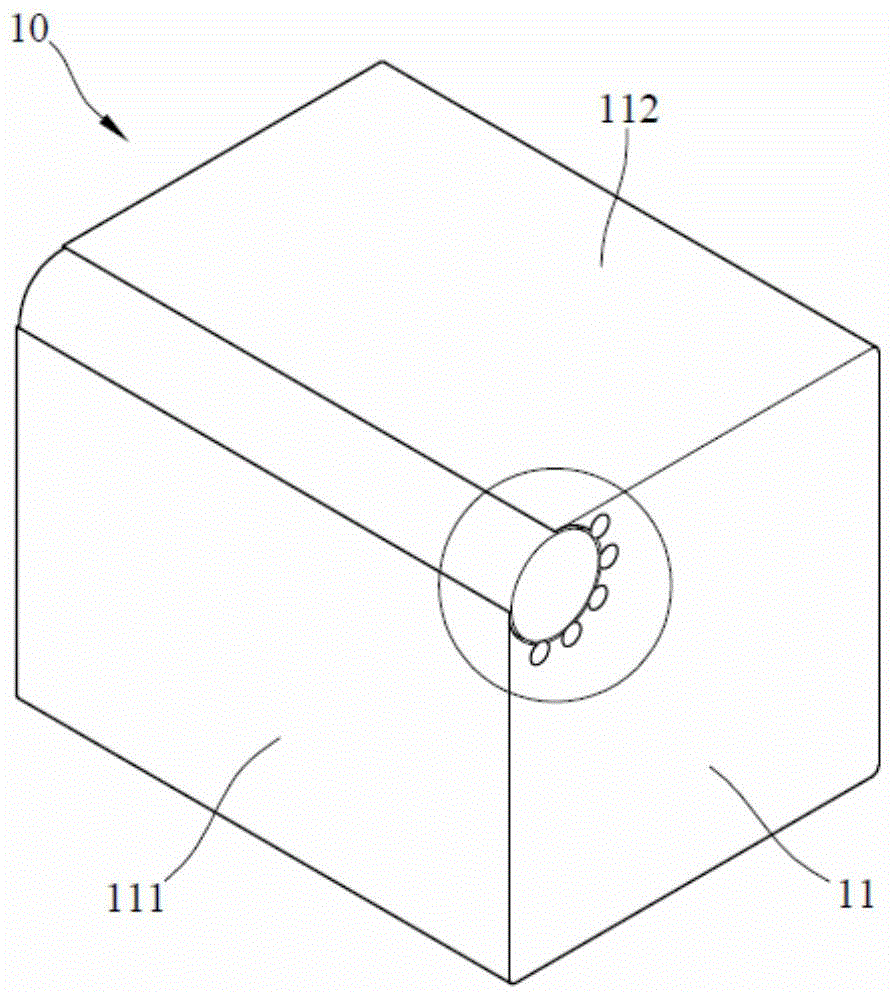
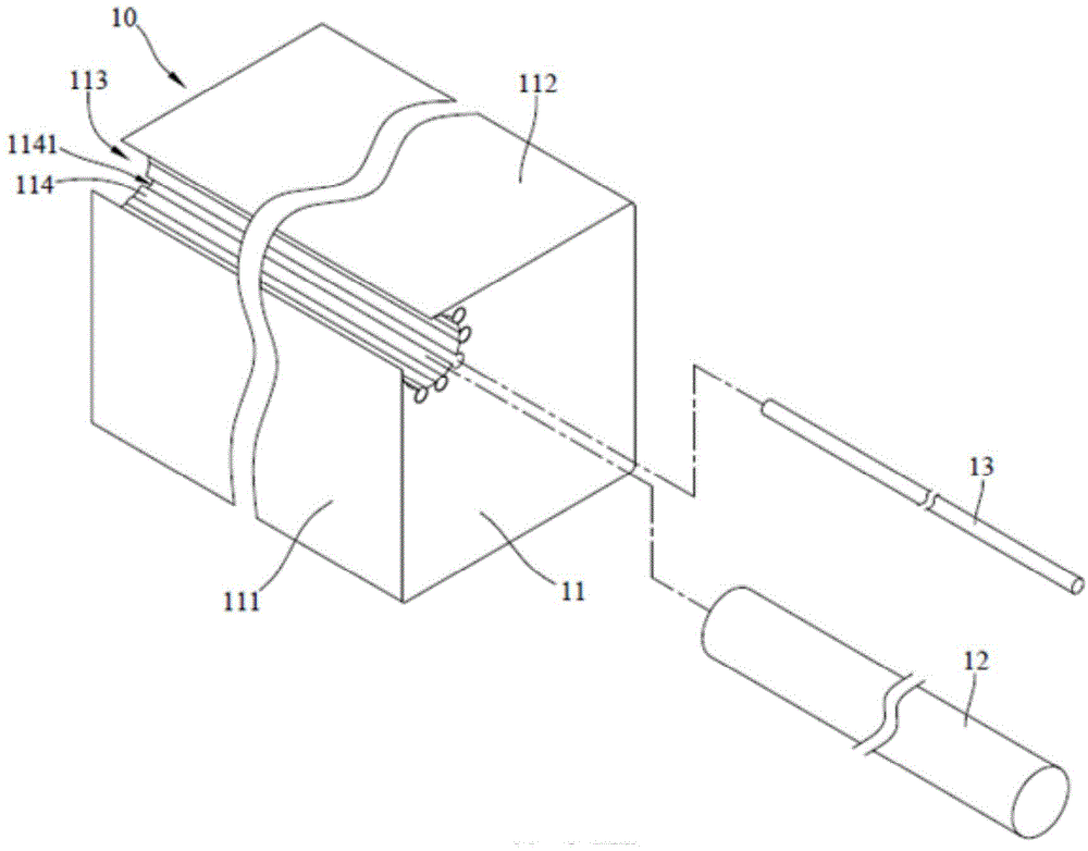
A stamping device comprises a bending insert, a bearing stripper plate and a puncher pin. The bending insert comprises a body, a rolling wheel and multiple rollers. The body is provided with a bending face, a top face and an embedding groove. The position where the bending face is adjacent to the top face forms a corner part of the body. The embedding groove is embedded in the corner part. Multiple grooves are formed in the inner wall of the embedding groove. The rolling wheel is embedded in the embedding groove. The rollers are arranged in the grooves, and a part of each roller protrudes out of the inner wall and makes contact with the rolling wheel. The bearing stripper plate is provided with a bearing face and is located on one side of the bending face. A height difference exists between the bearing face and the top face, so that a part of the bending face is exposed. The bearing face and a part of the bending face jointly form a bending work area. The puncher pin is located above the bearing face and corresponds to the bending work area.

Description

technical field [0001] The invention relates to a stamping equipment, in particular to a stamping equipment for stamping and bending. Background technique [0002] In the processing of metal products, bending sheet metal parts to make the sheet metal parts have a bending angle is an indispensable processing technology. The use of stamping equipment for bending processing is currently the mainstream method, but during the stamping process of traditional stamping and bending dies, due to the relative movement between the guide fillet of the bending block and the sheet metal part, the There will be friction between the fillet of the block and the contact surface of the sheet metal part, causing serious bending wear marks on the surface of the sheet metal part and affecting the appearance of the finished product. [0003] At present, the way to improve the bending wear marks left by stamping and bending dies on the surface of sheet metal parts in the industry is to use a new ty...

Claims


Application Information

Patent Timeline
Patent Type & Authority Applications(China)
IPC IPC(8): B21D5/01
CPCB21D5/01
Inventor 黄俊豪
Owner INVENTEC PUDONG TECH CORPOARTION
Learn More