
Combination-type slope surface flow testing device

A test device and slope flow technology, which is applied in the direction of measuring devices, instruments, scientific instruments, etc., can solve the problems of high economic cost and time cost of slope flow tests, difficulty in ensuring the consistency of repeated test conditions, damage to artificial vegetation and tank bottom plates and other issues, to achieve the effect of saving test cost, saving preparation time, and increasing the reuse rate

Inactive Publication Date: 2015-03-11
SICHUAN UNIV
View PDF2 Cites 6 Cited by
  • Summary
  • Abstract
  • Description
  • Claims
  • Application Information

AI Technical Summary

Problems solved by technology

However, since the slope flow test requires sand and artificial vegetation to be firmly attached to the bottom of the tank, it is very difficult to remove them, and often requires a lot of time and effort, and the operation of removing artificial vegetation is often difficult. It is destructive and can easily cause damage to artificial vegetation and the floor of the tank, which greatly reduces the reuse rate of artificial vegetation, shortens the service life of the tank, and increases the frequency of re-making artificial vegetation models, resulting in slope flow. The economic cost and time cost of the experiment is too high; moreover, there is often error in the sticking position of sand grains or artificial vegetation in repeated experiments, especially when simulating the combination of various slope roughness and various artificial vegetation distributions , it is difficult to ensure the consistency of repeated test conditions, which will affect the accuracy of test results

Method used


Image

  • Combination-type slope surface flow testing device
  • Combination-type slope surface flow testing device
  • Combination-type slope surface flow testing device

Examples


Embodiment 1

[0033] What present embodiment provides is the movable panel of 4 kinds of structures, specifically as follows:

[0034] 1. The active panel of the first structure

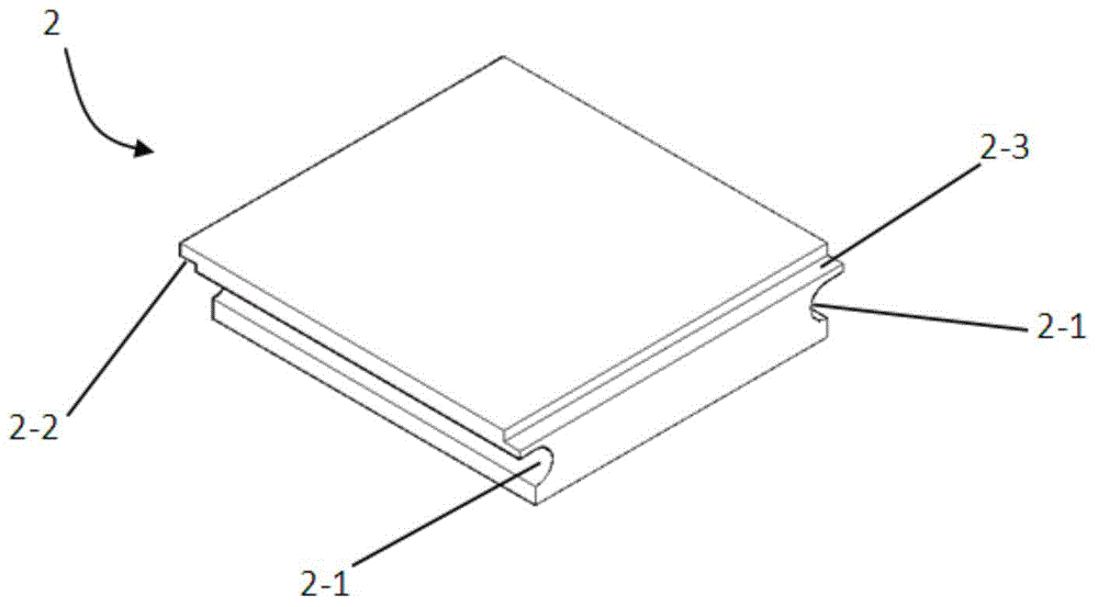
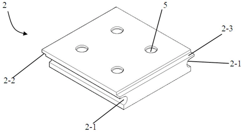
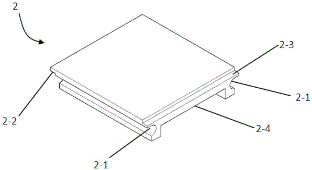
[0035] The structure diagram of the active panel 2 is as follows figure 1As shown, the movable panel is made of plastic and is a rectangular plate-shaped body, wherein a group of mutually parallel sides are respectively provided with "U"-shaped grooves 2-1 passing through the sides, and the height of the groove side at the lower end of the panel is less than The height of the edge of the groove located on one side of the upper end of the panel, and the other set of mutually parallel sides are respectively provided with upper convex strips 2-2 and lower stepped bosses 2-3; the top surface of the movable panel is a smooth surface or A rough surface formed by sand grains is pasted and fixed on the top surface.

[0036] 2. The active panel of the second structure

[0037] The structure diagram of the active panel 2...

Embodiment 2

[0043] Such as Figure 5 As shown, the combined slope flow test device given in this embodiment includes a slope water tank 1 , which is supported by pillars 12 to form an inclined structure, and also includes a movable panel 2 and matching connectors 3 . The water inlet and outlet openings of the slope water tank 1 are provided with anti-slip strips 4 on the bottom plate of the water outlet. The connector 3 includes two structures, respectively as Figure 6 , 7 As shown, the first structure is a strip, and the ends of one side of the strip are bilaterally symmetrically provided with convex lines, and the shape of the convex lines matches the shape of the "U" shaped groove 2-1 on the side of the movable panel; the second This kind of structure is also a strip body, and one side of the strip body is provided with a convex strip on one side, and the shape of the convex strip matches the shape of the "U" shaped groove 2-1 on the side of the movable panel. The movable panel 2 a...

Embodiment 3

[0045] The structure of the combined slope flow test device of this embodiment is basically the same as that of the device in embodiment 2, except that the movable panel of the first structure in embodiment 1 is used, and its top surface is rough.


PUM


Abstract

The invention provides a combination-type slope surface flow testing device. The combination-type slope surface flow testing device comprises a slope surface water tank which is supported by supporting columns to form an oblique structure. The combination-type slope surface flow testing device further comprises movable panels and connectors matched with the movable panels, anti-lip strips are arranged on an opening of a water inlet end and an opening of a water outlet end of the slope surface water tank and a bottom board of the water outlet end, the movable panels are connected with the connectors matched with the movable panels to form a combination slope surface and the combination slope surface is laid on the bottom board of the slope surface water tank. A slope surface flow test can be conducted with the device, the reuse rate of artificial vegetation can be increased, the service life of the slope surface water tank is prolonged, various slope surface conditions can be quickly replaced, and the time cost and the economic cost of the slope surface flow test are reduced.

Description

technical field [0001] The invention belongs to the technical field of slope flow test devices, in particular to a combined slope flow test device. Background technique [0002] Soil erosion is one of the problems that need to be solved urgently in the current social and economic development. According to the data of the third soil erosion census, the total area of ​​soil erosion in my country has reached 3.5692 million km 2 . Numerous studies have shown that overland flow is one of the main dynamic factors causing soil erosion. In order to deeply understand the characteristic mechanism of overland flow, it is necessary to conduct overland flow experiments. Slope flow tests can be roughly divided into two categories: one is directly carried out in the field, and the test results have good reliability, but because the boundary conditions of the slope surface in the test section are often very complicated, the test is highly accidental and it is difficult to repeat the test ...

Claims


Application Information

Patent Timeline
Patent Type & Authority Applications(China)
IPC IPC(8): G01N17/00
Inventor 王协康刘兴年刘同宦叶龙周苏芬
Owner SICHUAN UNIV
Learn More