
An ultrasonic flowmeter peak detection method and compensation system

A peak detection and ultrasonic technology, applied in the field of ultrasonic flowmeter measurement, can solve problems such as inaccurate measurement, and achieve the effects of improved accuracy, strong practicability, and simple structure

Active Publication Date: 2018-01-26
衡客仪器(大连)有限公司
View PDF4 Cites 0 Cited by
  • Summary
  • Abstract
  • Description
  • Claims
  • Application Information

AI Technical Summary

Problems solved by technology

[0003] The present invention aims to solve the inaccurate measurement problem caused by the forward conduction voltage drop of the diode and its serious temperature drift in the peak detection circuit of the ultrasonic flowmeter, and provides a method that can dynamically compensate the diode voltage drop in the peak detection circuit, so that It can measure the accurate peak value of the ultrasonic signal, so that it can be applied to the peak detection method of the ultrasonic flowmeter in the accurate calculation process of the ultrasonic flowmeter

Method used


Image

  • An ultrasonic flowmeter peak detection method and compensation system

Examples


Embodiment Construction

[0014] The present invention will be described in further detail below in conjunction with the accompanying drawings and specific embodiments.

[0015] The ultrasonic flowmeter peak detection method of the present invention comprises the following steps:

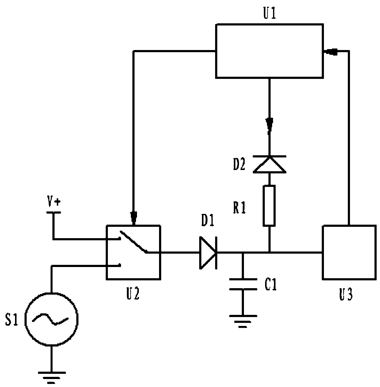
[0016] (1) Provide a reference voltage, measure the voltage on the capacitor, and calculate the difference between the voltage and the reference voltage to obtain the forward conduction voltage drop of the diode;

[0017] (2) When measuring the peak value of the normal ultrasonic signal, the voltage detected on the capacitor plus the forward conduction voltage drop of the diode obtained in step (1) is used as the peak signal voltage to calculate the flow rate.

[0018] The principle diagram of the compensation system for the peak detection of the ultrasonic flowmeter for realizing the above-mentioned detection method in the present invention is as follows figure 1 As shown, it includes MCU module U1, diode D1, electronic sw...


PUM


Abstract

The invention discloses an ultrasonic flowmeter peak detection method and a compensation system, which can dynamically compensate the diode voltage drop in the peak detection circuit, so that it can detect the accurate peak value of the ultrasonic signal, and thus can be applied to the precise calculation process of the ultrasonic flowmeter. Detection method and compensation system. The method includes the following steps: providing a reference voltage, measuring the voltage on the capacitor, and calculating the difference between the voltage and the reference voltage to obtain the forward conduction voltage drop of the diode; The obtained voltage plus the obtained diode forward conduction voltage drop is used as the signal peak voltage to calculate the flow rate. The method and system of the invention can dynamically compensate the diode voltage drop in the peak detection circuit, so that it can detect the accurate peak value of the ultrasonic signal, and thus can be applied to the precise operation process of the ultrasonic flowmeter, improving the accuracy of the flowmeter.

Description

technical field [0001] The invention relates to the field of ultrasonic flowmeter measurement, in particular to an ultrasonic flowmeter peak detection method and a compensation system for ultrasonic flowmeter peak detection. Background technique [0002] Ultrasonic flowmeter is a flowmeter that measures flow through the time difference or frequency difference of ultrasonic signals propagating in the fluid. The most important part is the processing and measurement of ultrasonic signals, and the peak detection of ultrasonic signals is the process of ultrasonic signal processing. A commonly used measurement method. At present, for the peak detection of ultrasonic signals, most of them use a simple peak detection circuit, that is, use the unidirectional conduction characteristic of the diode, use the capacitor to store the peak value of the ultrasonic signal, and then measure the voltage value stored in the capacitor as the peak value of the ultrasonic signal. This method has o...

Claims


Application Information

Patent Timeline
Patent Type & Authority Patents(China)
IPC IPC(8): G01F1/66G01H11/06
Inventor 李蕊董旭李长奇丛萌郭桂梅梁艳书
Owner 衡客仪器(大连)有限公司
Learn More