
Centrifugal Fan Combined Air Purifier

An air purifier and centrifugal fan technology, applied in heating methods, air conditioning systems, air flow control components, etc., can solve the problems of uneven air intake through the filter screen, scattered air outlet, and low wind pressure of axial fans, so as to avoid local problems. Air circulation, improved filter efficiency, and directional flow

Active Publication Date: 2017-09-22
SHENZHEN PUREMATE TECH
View PDF8 Cites 0 Cited by
  • Summary
  • Abstract
  • Description
  • Claims
  • Application Information

AI Technical Summary

Problems solved by technology

[0002] Most of the existing air purifiers use axial flow fans or centrifugal fans to push the air flow to achieve air purification. The volume of a single fan is relatively large, so the volume of the air purifier is correspondingly designed to be larger, and at the same time, the Noise is also relatively large
On the other hand, the air inlet of the filter is relatively concentrated near the air inlet of the wind wheel, resulting in uneven air inlet to the filter and affecting the life of the filter.
[0003] Chinese patent CN201120099772 discloses an air purifier composed of a plurality of axial flow fans, which has the characteristics of small size, but the axial flow fan has a small wind pressure, and only some purification nets with small air resistance can be used. To increase the air volume, only Increased speed results in loud noise
However, because the air outlet is on both sides of the frame, the air outlet is scattered and the wind force becomes smaller, and because the air inlet and the air outlet direction form an angle of 90 degrees, it is easy to form a local air circulation (the fresh air discharged quickly enters the air inlet. ) affects the purification efficiency, and at the same time, only two rows of fans can be used due to the use of two sides of the air outlet, so that it is impossible to design a purification device with a larger air volume. These defects also affect its popularization and application

Method used


Image

  • Centrifugal Fan Combined Air Purifier
  • Centrifugal Fan Combined Air Purifier
  • Centrifugal Fan Combined Air Purifier

Examples

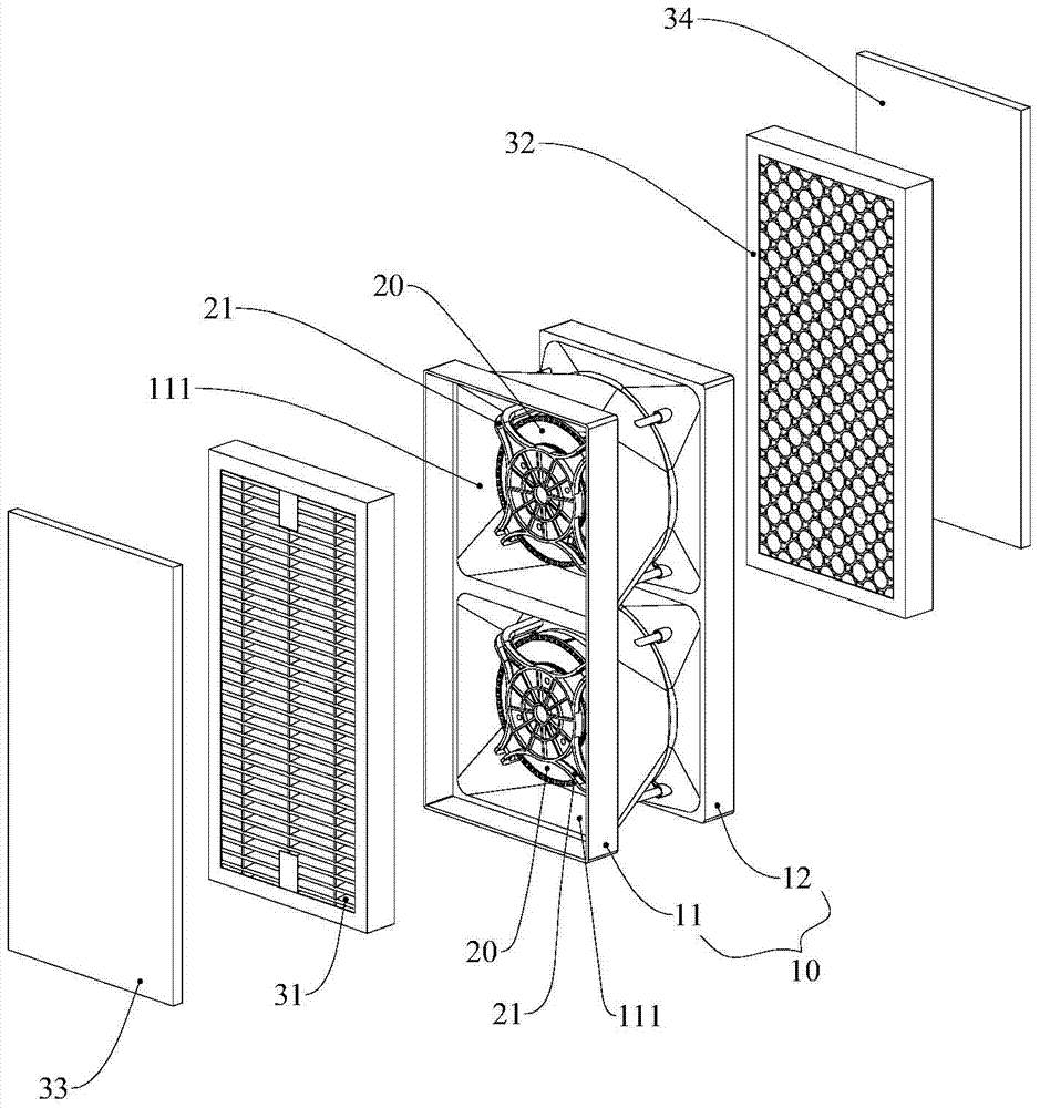
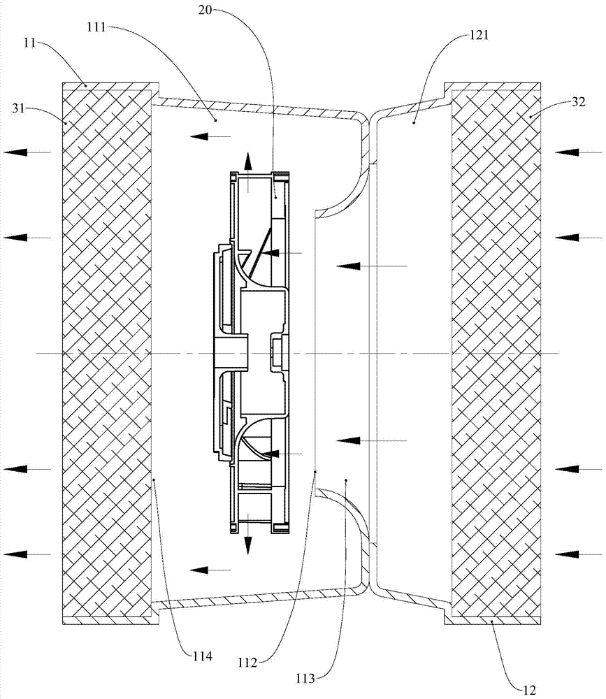

Embodiment Construction

[0026] In order to fully understand the technical content of the present invention, the technical solutions of the present invention will be further introduced and illustrated below in conjunction with specific embodiments.

[0027] The specific structure of the first embodiment of the present invention is as figure 1 with figure 2 shown.

[0028] The air purifier includes a frame body 10 and a centrifugal fan 20 and a filter net arranged on the frame body 10 . The filter screen of this embodiment can filter and purify particulate matter, organic chemical pollutants and germs.

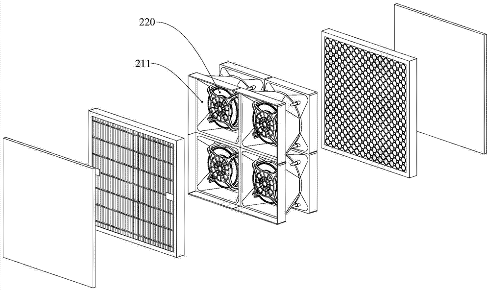
[0029] The frame body 10 includes a front frame body 11 and a rear frame body 12 which are fixedly connected to each other. An air duct 111 for accommodating a centrifugal fan 20 is provided on the front frame body 11 . The centrifugal fan 20 is fixed in the middle of the air duct 111 through the mounting frame 21 . In this embodiment, there are two centrifugal fans 20 , so there are also two air...


PUM


Abstract

A centrifugal fan combined air purifier comprises a frame (10), centrifugal fans (20) and filter screens (31, 32), wherein the centrifugal fans (20) and the filter screens (31, 32) are arranged on the frame (10). More than one centrifugal fan (20) is provided. The frame (10) comprises a front frame (11), and air ducts (111) for accommodating the centrifugal fans (20) are arranged on the front frame (11). More than one air duct (111) is provided. The air ducts (111) are arranged side by side in the same vertical plane, the central axis of each air duct (111) is perpendicular to the vertical plane, the air inlet direction of each air duct (111) is the same as the air outlet direction of the air duct (111) and is parallel to the central axis of the air duct (111), and the central axis of each centrifugal fan (20) coincides with that of each air duct (111). When the air purifier works, air enters the centrifugal fans (20) from air inlets (112) of the air ducts (111), and air exhausted from the centrifugal fans (20) is gathered in the air ducts (111) to form positive pressure and then sprayed out from air outlets (114) of the air ducts (111).

Description

technical field [0001] The invention relates to air cleaning equipment, in particular to a centrifugal fan combined air cleaner. Background technique [0002] Most of the existing air purifiers use axial flow fans or centrifugal fans to push the air flow to achieve air purification. The volume of a single fan is relatively large, so the volume of the air purifier is correspondingly designed to be larger, and at the same time, the The noise is also relatively loud. On the other hand, the filter near the air inlet of the wind wheel relatively concentrates the air intake, resulting in uneven air intake to the filter and affecting the life of the filter. [0003] Chinese patent CN201120099772 discloses an air purifier composed of a plurality of axial flow fans, which has the characteristics of small size, but the axial flow fan has a small wind pressure, and only some purification nets with small air resistance can be used. To increase the air volume, only Increased speed resu...

Claims


Application Information

Patent Timeline
Patent Type & Authority Patents(China)
IPC IPC(8): F24F5/00F24F13/28F24F13/08
CPCF24F13/08F24F13/28F24F8/10F24F8/108F24F5/00
Inventor 严义清李祥武严方升
Owner SHENZHEN PUREMATE TECH
Learn More