Eureka AIR delivers breakthrough ideas for toughest innovation challenges, trusted by R&D personnel around the world.

In-situ self-inspection and metering device and method of automatic test system

A technology of automatic test system and metering device, applied in the direction of measuring device, measuring electricity, measuring electric variables, etc. The results lack integrity and authenticity, and achieve the effect of improving system mobility, shortening the measurement cycle, and meeting the needs of automation and informatization

Inactive Publication Date: 2015-02-25
SHANGHAI RADIO EQUIP RES INST
View PDF3 Cites 10 Cited by
  • Summary
  • Abstract
  • Description
  • Claims
  • Application Information

AI Technical Summary

Problems solved by technology

The traditional off-position measurement method regards the test system as a combination of independent test instruments, ignores the changes in test signals caused by the internal connection cables, switches, loads, etc. of the test system, and cannot examine the performance indicators of instruments and meters in the test system, and cannot meet the requirements of the system. Reliability and accuracy requirements, measurement results lack integrity and authenticity
At the same time, off-position measurement needs to periodically disassemble the test instrument from the test system, which will also cause unnecessary wear and shutdown of the system connector
The data processing and recording of the measurement for independent instruments and meters in the off-site measurement cannot meet the needs of automation and informatization

Method used


Image

  • In-situ self-inspection and metering device and method of automatic test system
  • In-situ self-inspection and metering device and method of automatic test system
  • In-situ self-inspection and metering device and method of automatic test system

Examples


Embodiment Construction

[0037] The present invention will be further elaborated below by describing a preferred specific embodiment in detail in conjunction with the accompanying drawings.

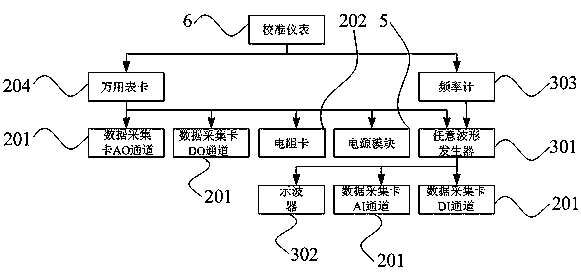
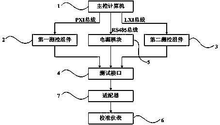
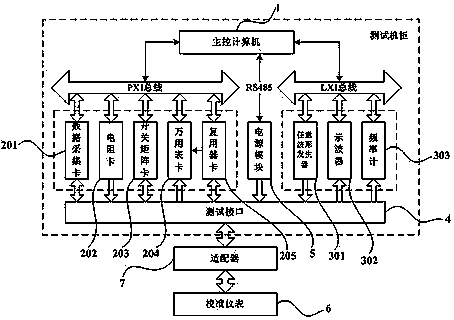
[0038] like figure 1 and figure 2 As shown, an in-situ self-checking and metering device of an automatic test system is based on the PXI and LXI hybrid bus architecture, including: a main control computer 1, which is provided by the automatic test system itself, and has a PXI bus controller and an Ethernet interface; A measurement and control component 2 is connected with the main control computer 1 through the PXI bus; a second measurement and control component 3 is connected with the main control computer 1 through the LXI bus; a test interface 4 is connected with the first measurement and control component 2 and the second measurement and control component respectively. Two measurement and control components 3 are connected; power module 5 (six program-controlled DC power supply), based on RS485 bus, one end...


PUM


Abstract

The invention discloses an in-situ self-inspection and metering device of an automatic test system. The in-situ self-inspection and metering device of the automatic test system comprises a main control computer, a first measurement and control module, a second measurement and control module, a test interface, a power module and a calibration instrument. The first measurement and control module is connected with the main control computer through a PXI bus. The second measurement and control module is connected with the main control computer through an LXI bus. The test interface is connected with the first measurement and control module and the second measurement and control module respectively. One end of the power module is connected with the main control computer, and the other end of the power module is connected with the test interface. The calibration instrument is connected with the test interface. The invention further provides an in-situ self-inspection and metering method. According to the in-situ self-inspection and metering device and the in-situ self-inspection and metering method of the automatic test system, the accuracy and the reliability of self-inspection results can be improved effectively, the self-inspection and metering period of the system is shortened, and the automation and informatization needs are met.

Description

technical field [0001] The invention relates to an in-situ self-checking and metering device and method of an automatic test system. Background technique [0002] As a comprehensive integrated test system, the automatic test system provides incentives for the object under test with the overall technical indicators, and measures the input response of the object under test. The system accuracy index is affected by factors such as PXI chassis, EMC (electromagnetic compatibility) performance, system power supply, cooling and programming. The traditional off-position measurement method regards the test system as a combination of independent test instruments, ignores the changes in test signals caused by the internal connection cables, switches, loads, etc. of the test system, and cannot examine the performance indicators of instruments and meters in the test system, and cannot meet the requirements of the system. Reliability and accuracy requirements, measurement results lack in...

Claims


Application Information

Patent Timeline
IPC IPC(8): G01R31/00G01R35/00
Inventor 那丽丽冯云曲海山王哲刘鑫光龚明
Owner SHANGHAI RADIO EQUIP RES INST
Why Eureka
Eureka Blog
Learn More