An automatic boxing device

A technology of boxing and equipment, applied in the field of automatic boxing equipment, can solve the problems of unsuitable ground space, complex equipment structure, low boxing speed, etc., meet the needs of boxing actions, have a wide range of applications, and improve production efficiency Effect

Inactive Publication Date: 2015-11-18
HEFEI UNIV OF TECH
View PDF3 Cites 0 Cited by
  • Summary
  • Abstract
  • Description
  • Claims
  • Application Information

AI Technical Summary

Problems solved by technology

However, most of the existing equipment has a small controllable stroke, low packing speed, complex equipment structure, and a large footprint. It requires manual assistance to complete the movement of the packing box. It is not suitable for production workshops with limited floor space and large travel requirements for packing boxes.

Method used


Image

  • An automatic boxing device
  • An automatic boxing device
  • An automatic boxing device

Examples


Embodiment Construction

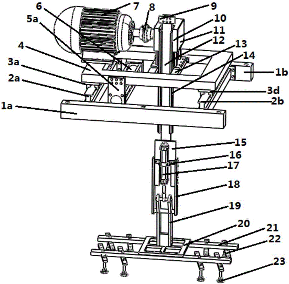
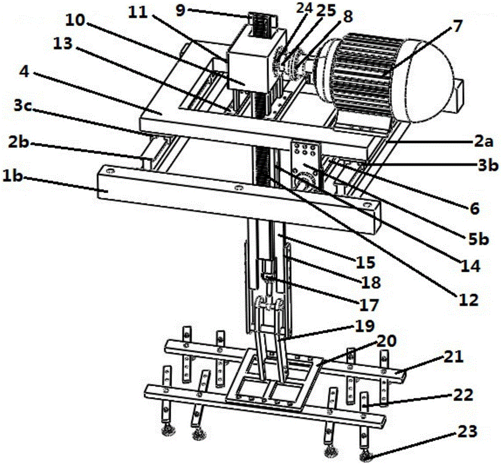
[0030] see figure 1 and figure 2 , an automatic boxing device comprising: a horizontal feed mechanism, a rack and pinion mechanism, a turning mechanism and an air sucker mechanism;

[0031] figure 1 and figure 2 As shown, the composition of the horizontal feed mechanism includes a beam-shaped front base 1a, a beam-shaped rear base 1b, a feed cylinder 6, a left feed guide rail 2a, a right feed guide rail 2b, and a left lower guide rail seat 3a and a left upper guide rail seat 3b. The left guide rail seat, the right guide rail seat formed by the upper right guide rail seat 3c and the right lower guide rail seat 3d, the back-shaped support 4 and the cylinder fixed plate formed by the cylinder tail end fixed plate 5a and the cylinder head fixed plate 5b;

[0032] A left feed guide rail 2a and a right feed guide rail 2b are arranged between the two ends of the beam-shaped front base 1a and the beam-shaped rear base 1b, thereby forming a rectangular seat; The right guide rail ...


PUM


Abstract

The invention discloses an automatic box encasement device. The automatic box encasement device is characterized by comprising a horizontal feeding mechanism, a gear and rack mechanism, an overturning mechanism and an air suction cup mechanism; the horizontal feeding mechanism pushes left and right guide rails to achieve feeding in the horizontal direction along guide rail bases through a feeding air cylinder; according to the gear and rack mechanism, a motor in the horizontal position drives a gear shaft to rotate, and therefore a rack meshed with the gear shaft is driven to rapidly move in the vertical direction; the overturning mechanism drives a suction cup supporting frame through stretching and retracting of an overturning air cylinder to be turned over by 90 degrees; according to the air suction cup mechanism, air suction and grasping of packaging boxes are achieved through an air suction cup with the adjustable position. According to the automatic box encasement device, air suction, grasping, horizontal feeding, large-stroke vertical movement and 90-degree overturning of packaging boxes of various sizes can be effectively achieved, large-stroke encasement of the various packaging boxes can be rapidly and efficiently completed, and the automatic box encasement device is simple in structure, can be arranged above a production line and saves floor space.

Description

technical field [0001] The invention relates to an automatic box-fitting device, in particular to an automatic box-fitting device for lifting and flipping a product packaging box on a production line and putting it on a product. Background technique [0002] In the production of machinery, electronics, food and other industries, due to the needs of product packaging technology, it is often necessary to quickly pack products. However, most of the existing equipment has a small controllable stroke, low packing speed, complex equipment structure, and a large footprint. It requires manual assistance to complete the movement of the packing box. It is not suitable for production workshops with limited floor space and large travel requirements for packing boxes. . Contents of the invention [0003] In order to overcome the shortcomings of the above-mentioned prior art, the present invention proposes an automatic case-packing device applied to automatic production line packing, w...

Claims


Application Information

Patent Timeline
Patent Type & Authority Patents(China)
IPC IPC(8): B65B43/46B65B5/04
CPCB65B5/04B65B43/46
Inventor 赵韩黄青青黄康郜欣欣朱晓慧晏伟清
Owner HEFEI UNIV OF TECH
Why Eureka
Try Eureka