
Electric heating pot

An electric heating pot and pot body technology, which is applied in the directions of cooking utensils, cooking utensils, household appliances, etc., can solve the problems that the pot lid cannot be separated from the pot body, the cleaning of the electric heating pot is inconvenient, and the life of the electric control element is affected, and the volume is reduced. and complexity, improve lifespan, and the effect of accurate signal transmission

Active Publication Date: 2015-02-25
JOYOUNG CO LTD
View PDF5 Cites 6 Cited by
  • Summary
  • Abstract
  • Description
  • Claims
  • Application Information

AI Technical Summary

Problems solved by technology

[0003] In the process of using the above-mentioned electric heating pot, the inventor found that since the power board and the heating device are both arranged in the pot body, and the distance between them is relatively close, the heating device will emit a large amount of heat when it is working, which will affect the electric control elements on the power board At the same time, since the temperature measuring device on the pot cover is electrically connected to the power board through wires, the pot cover cannot be separated from the pot body, that is, the pot cover cannot be taken away from the pot body for cleaning separately, thus affecting the electric heating pot. Inconvenience for cleaning

Method used


Image

  • Electric heating pot
  • Electric heating pot
  • Electric heating pot

Examples


no. 1 example

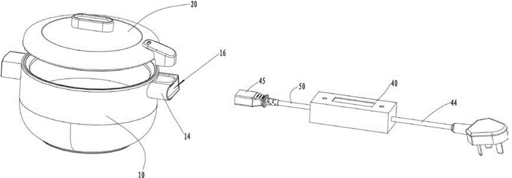
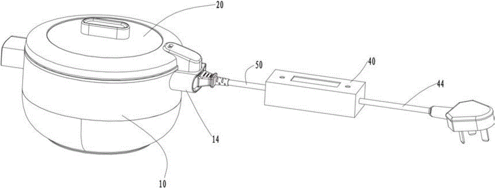
[0042] The invention provides an electric heating pan, please refer to Figure 1-Figure 5b , the electric heating pot includes a pot body 10 and a pot cover 20, the pot cover 20 is detachably arranged on the pot body 10, the pot body 10 is provided with an inner container 11, a heating device 12 and a heating terminal 13, the The heating device 12 is located below the inner container 11 to heat the inner container 11, the heating terminal 13 is electrically connected to the heating device 12 through wires, the pot cover 20 and the inner container 11 form a cooking cavity 30, The pot cover 20 is provided with a first temperature measuring device 21 and a first wireless transmitting terminal 22 electrically connected to the first temperature measuring device 21, and the first temperature measuring device 21 passes the measured temperature signal of the cooking cavity 30 through The first wireless transmitting terminal 22 sends out.

[0043] The electric heating pot also include...

no. 2 example

[0060] Image 6 It is a sectional view of the electric heating pan according to the second embodiment of the present invention, Image 6 structure with image 3 The structures are similar, so the same element symbols represent the same elements. The main difference between this embodiment and the first embodiment is that the pot body is provided with a second temperature measuring device.

[0061] Please refer to Figure 6-Figure 7 , in this embodiment, the pot body 10 is provided with a second temperature measuring device 17 for detecting the temperature of the inner tank 11, the second temperature measuring device 17 is a thermistor, and the thermistor can be used to Detect the bottom temperature of the inner container 11 or be used to detect the side wall temperature of the inner container 11, the pot body 10 is also provided with a second wireless transmitting terminal 18 electrically connected to the second temperature measuring device 17, the The second wireless trans...

no. 3 example

[0065] Figure 8 It is an exploded diagram of the electric heating pan of the third embodiment of the present invention, Figure 8 structure with figure 1 The structures are similar, so the same component symbols represent the same components. The main difference between this embodiment and the first embodiment is that the connector is located on the control box.

[0066] See Figure 8 , Figure 9 with Figure 4 , in this embodiment, the connector 45 is directly mounted on the control box 40, the power terminal 42 and the first wireless receiving terminal 43 are arranged on the connector 45, the power terminal 42 and the first wireless The receiving terminals 43 are respectively electrically connected to the power board 41 , the power supply terminals 42 are plugged with the heating terminals 13 , and the first wireless receiving terminals 43 are electromagnetically coupled to the first wireless transmitting terminals 22 .

[0067] In this embodiment, the connector 45 is ...


PUM


Abstract

The invention discloses an electric heating pot. The electric heating pot comprises a pot body and a pot cover which is separably arranged on the pot body, wherein a liner, a heating device and a heating terminal electrically connected with the heating device are arranged in the pot body, and the pot cover is provided with a first temperature measurement device and a first wireless transmitting terminal electrically connected with the first temperature measurement device. The electric heating pot further comprises a control box separated from the pot body and an insertion piece inserted in the upper end of the pot body, wherein a power panel is arranged in the control box, a power terminal and a first wireless receiving terminal which are electrically connected with the power panel are arranged on the insertion piece, the power terminal is electrically connected with the heating terminal in an inserted mode, the first wireless receiving terminal corresponds to the first wireless transmitting terminal, the first wireless receiving terminal receives a temperature signal transmitted by the first wireless transmitting terminal and sends the temperature signal to the power panel, and the distance between the first wireless receiving terminal and the first wireless transmitting terminal is smaller than 50 mm.

Description

technical field [0001] The invention relates to the field of kitchen cooking utensils, in particular to an electric heating pot with an external power board. Background technique [0002] Existing electric heating pots, such as electric rice cookers, electric pressure cookers or electric stewers, generally include a pot body and a pot cover. The pot body is provided with an inner container, a power board, and a heating device, and the pot cover and the inner container form a cooking cavity. Generally, the pot cover is equipped with a temperature measuring device. The temperature measuring device is used to measure the temperature in the cooking cavity. board, the power board controls the electric heating pan. [0003] In the process of using the above-mentioned electric heating pot, the inventor found that since the power board and the heating device are both arranged in the pot body, and the distance between them is relatively close, the heating device will emit a large am...

Claims


Application Information

Patent Timeline
Patent Type & Authority Applications(China)
IPC IPC(8): A47J27/00A47J36/06A47J36/00
Inventor 朱泽春祝峰余星光王翔
Owner JOYOUNG CO LTD
Learn More