Hollow wall winding pipe connecting structure

A connection structure and winding tube technology, which is applied in the field of mechanical parts, can solve the problems of easy movement of sealing rings, displacement of sealing rings, water leakage or oil leakage, etc., and achieve the effect of preventing sliding and ensuring reliability

Inactive Publication Date: 2015-02-11
HUBEI BADATONG NEW MATERIAL APPL TECH
View PDF6 Cites 10 Cited by
  • Summary
  • Abstract
  • Description
  • Claims
  • Application Information

AI Technical Summary

Problems solved by technology

[0005] The disadvantage of this connection method is that the sealing of the joint is not good, and water or oil leakage is prone to occur. Therefore, in order to improve the sealing, a sealing ring will be provided between the connecting sleeve and the pipe fitting bracket to be connected, but after long-term use, the sealing The ring is easy to move, especially when the diameter of the pipe to be connected is large and the pressure inside the pipe is high, the displacement of the sealing ring is obvious

Method used


Image

  • Hollow wall winding pipe connecting structure
  • Hollow wall winding pipe connecting structure
  • Hollow wall winding pipe connecting structure

Examples


Embodiment Construction

[0030] In order to express the present invention more clearly, the present invention will be further described below in conjunction with the accompanying drawings.

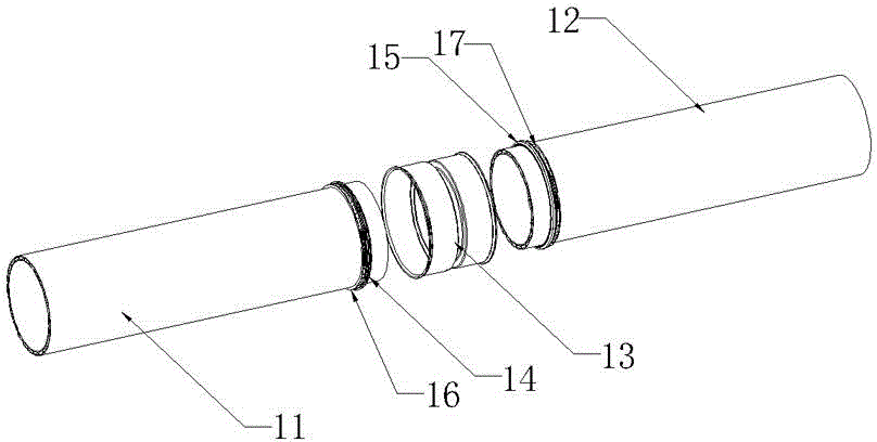
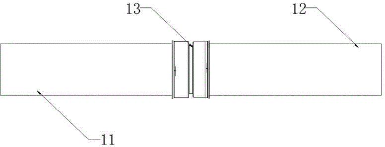
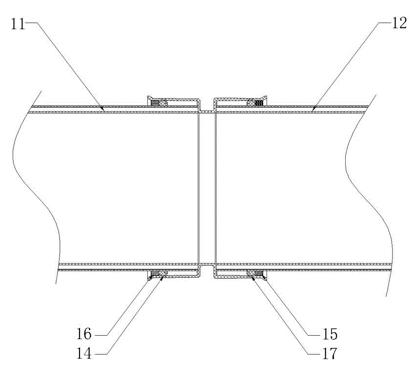
[0031] see Figure 1-4 , the hollow wall winding pipe connection structure provided by the present invention includes a first pipe piece 11, a second pipe piece 12, a connecting sleeve 13, a first sealing ring 14, a second sealing ring 15, a first positioning clip 16 and a second positioning Clamp 17; the first pipe fitting 11 is inserted at one end of the connecting sleeve 13, the first sealing ring 14 and the first positioning clip 16 are set on the first pipe fitting 11, the first sealing ring 14 and the first positioning clip 16 They are all located between the outer wall of the first pipe fitting 11 and the inner wall of the connecting pipe sleeve 13, the first positioning hoop 16 is close to the outside of the first sealing ring 14; the second pipe fitting 12 is inserted in the other end of the connecting pi...


PUM


Abstract

The invention discloses a hollow wall winding pipe connecting structure which comprises a first pipe fitting, a second pipe fitting, a connecting pipe sleeve, two sealing rings and two positioning hoops; the first pipe fitting is mounted and inserted into one end of the connecting pipe sleeve, the first pipe fitting is sleeved and equipped with the first sealing ring and the first positioning hoop, the first sealing ring and the first positioning hoop are both arranged between the outer wall of the first pipe fitting and the inner wall of the connecting pipe sleeve, and the first positioning hoop is clung to the outer side of the first sealing ring; the second pipe fitting is mounted and inserted into the other end of the connecting pipe sleeve, the second pipe fitting is sleeved and equipped with the second sealing ring and the second positioning hoop, the second sealing ring and the second positioning hoop are both arranged between the outer wall of the second pipe fitting and the inner wall of the connecting pipe sleeve, and the second positioning hoop is clung to the outer side of the second sealing ring. According to the structure, the sealing rings are arranged between the pipe fittings and the connecting pipe sleeve, and the positioning hoops are further mounted to be propped against the two sealing rings, so that the sealing rings can be effectively prevented from sliding on the pipe fittings, and the sealing reliability is ensured.

Description

[0001] technical field [0002] The invention relates to the field of mechanical parts, in particular to a connection structure of a hollow wall winding pipe. [0003] Background technique [0004] In the prior art, there are many ways to connect pipe fittings. The simplest one is to use a connecting sleeve to connect two pipe fittings: one end of the connecting sleeve is connected to one pipe fitting, and the other end is connected to the other pipe fitting. This connection method is simple in structure and convenient in connection, so it is the most widely used. [0005] The disadvantage of this connection method is that the sealing of the joint is not good, and water or oil leakage is prone to occur. Therefore, in order to improve the sealing, a sealing ring will be provided between the connecting sleeve and the pipe fitting bracket to be connected, but after long-term use, the sealing The sealing ring is easy to move, especially when the diameter of the pipe to be conn...

Claims


Application Information

Patent Timeline
Patent Type & Authority Applications(China)
IPC IPC(8): F16L21/00
CPCF16L21/00
Inventor 夏超高云照刘远见李宁
Owner HUBEI BADATONG NEW MATERIAL APPL TECH
Why Eureka
Try Eureka