Liquid ejecting apparatus and wiping method

一种喷射装置、液体喷射部的技术,应用在印刷等方向,能够解决附着于托架或头主体的侧面上等问题

Active Publication Date: 2015-02-11
SEIKO EPSON CORP
View PDF7 Cites 3 Cited by
  • Summary
  • Abstract
  • Description
  • Claims
  • Application Information

AI Technical Summary

Problems solved by technology

Therefore, since the wiper is pressed by the corners of the carriage and the head main body, there is a problem that the ink attached to the wiper adheres to the side of the carriage or the head main body.

Method used


Image

  • Liquid ejecting apparatus and wiping method
  • Liquid ejecting apparatus and wiping method
  • Liquid ejecting apparatus and wiping method

Examples


Embodiment Construction

[0031] Hereinafter, an embodiment in which a liquid ejecting device is embodied as an inkjet printer will be described with reference to the drawings.

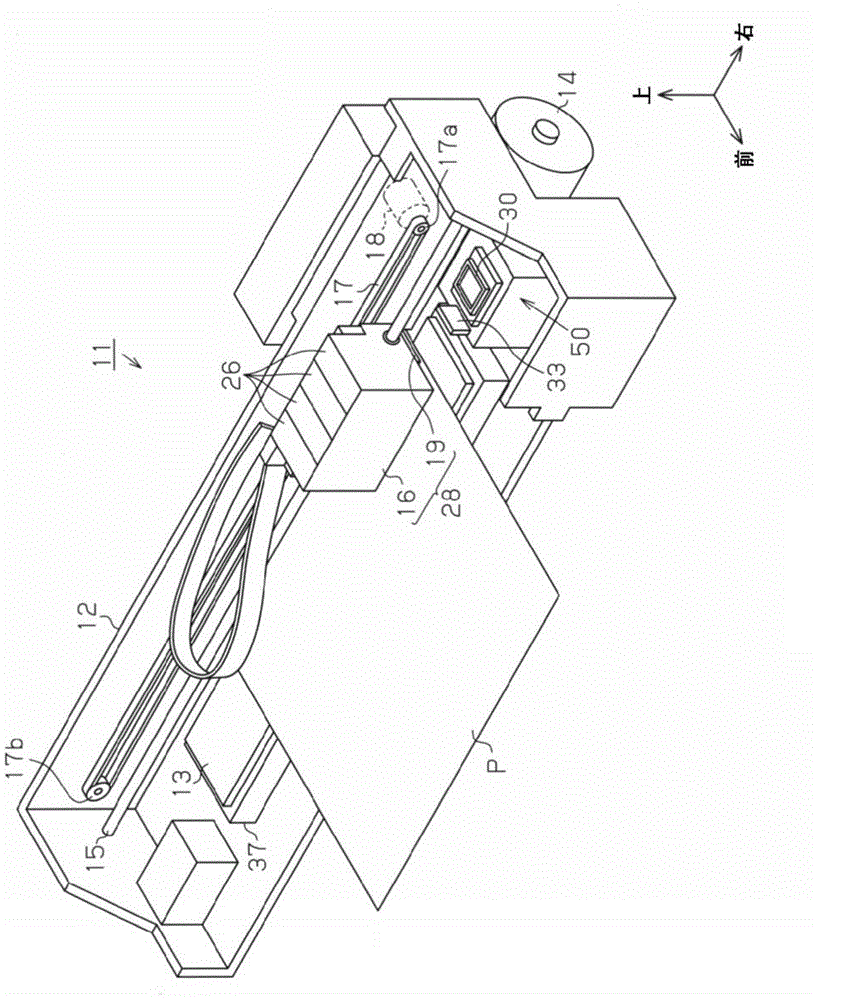
[0032] Such as figure 1 As shown, an inkjet printer 11 as an example of a liquid ejecting device includes a substantially box-shaped main body casing 12 having a substantially rectangular box shape. In the lower part of the main body casing 12, the support stand 13 is extended along the longitudinal direction, ie, the left-right direction. The paper P is fed from the rear side onto the support table 13 by a paper feeding mechanism not shown, driven by a paper feeding motor 14 provided on the lower rear surface of the main body casing 12 .

[0033]Above the support base 13 in the main body casing 12 , a guide shaft 15 is bridged along the longitudinal direction of the support base 13 , that is, the left-right direction. A carriage 16 is supported on the guide shaft 15 so as to be reciprocable along the guide shaft 15 . A dri...


PUM


Abstract

A liquid ejecting apparatus includes a liquid ejecting unit which includes a nozzle forming surface having nozzle openings for ejecting liquid formed thereon, a wiper which is contactably disposed on the nozzle forming surface, a movement unit which is able to relatively move the liquid ejecting unit and the wiper, and a control unit which controls the movement units such that an interference amount of the wiper and the nozzle forming surface in a position of the wiper which comes in contact with the liquid ejecting unit, is smaller than an interference amount of the wiper and the nozzle forming surface when the wiper is relatively moved through a nozzle region which is a region including the nozzle openings of the nozzle forming surface in a direction along the nozzle forming surface.

Description

technical field [0001] The present invention relates to a liquid ejecting device such as an inkjet printer and a wiping method in the liquid ejecting device. Background technique [0002] Generally, as a liquid ejecting device, there is known an ink jet that ejects ink (liquid) from a nozzle formed by forming an opening on a nozzle forming surface of a liquid ejecting head (liquid ejecting unit) to a recording medium such as paper to perform printing. type printer. Such printers are generally provided with a head maintenance device for maintaining the ejection characteristics of ink from the liquid ejection head. [0003] Such head maintenance devices have various functions. For example, there is a function of recovering the ink ejection characteristics from the nozzles by capping the nozzle forming surface of the liquid ejection head with the suction cap and sucking the thickened ink from the nozzles with the suction pump. In addition, it has a function of wiping (wiping...

Claims


Application Information

Patent Timeline
Patent Type & Authority Applications(China)
IPC IPC(8): B41J2/01B41J2/165
CPCB41J2/16538B41J2/16535B41J2/16541
Inventor 间野隆志
Owner SEIKO EPSON CORP
Why Eureka
Try Eureka