Steel bending machine

A technology for bending and fuselage of steel bars, applied in the field of steel bar bending machines, can solve the problems of not being able to control the bending angle of steel bars well, and the scope of application is narrow, and achieve the effect of avoiding sliding, convenient bending angle, and expanding the scope of application

Inactive Publication Date: 2016-02-24
SICHUAN DINGRUI HYDRAULIC EQUIP MFR
View PDF4 Cites 2 Cited by
  • Summary
  • Abstract
  • Description
  • Claims
  • Application Information

AI Technical Summary

Problems solved by technology

However, this steel bar bending machine cannot control the bending angle of the steel bar very well, and in addition, it can only bend the steel bar to a certain fixed value of the bending radius of curvature, so the scope of application is narrow

Method used


Image

  • Steel bending machine
  • Steel bending machine
  • Steel bending machine

Examples


Embodiment 1

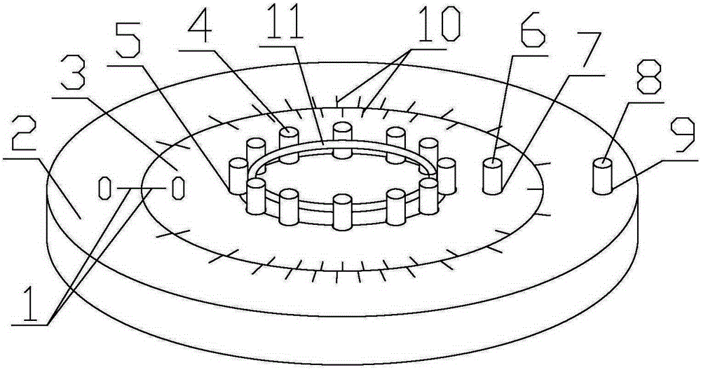
[0024] A steel bar bending machine, such as figure 1 As shown, including the fuselage and the working plate on top of the fuselage. The working disk includes a fixed disk 2 on the outside and a rotating disk 3 on the inside of the fixed disk 2, and the fixed disk 2 is connected with the fuselage and fixed. The rotating disk 3 is connected with the driving device inside the fuselage, and the driving device can drive the rotating disk 3 to rotate around its own axis. A number of positioning shaft holes 5 and clamping shaft holes 7 are evenly distributed on the rotating disc 3 along the circumferential direction of the rotating disc 3, and the distance between the positioning shaft holes 5 and the clamping shaft holes 7 is adapted to the diameter of the steel bar to be bent , a number of positioning shaft holes 5 are distributed in a circle on the rotating disk 3, and the center of the circularly distributed positioning shaft holes 5 coincides with the center of the rotating dis...

Embodiment 2

[0027] On the basis of Embodiment 1, scale lines 10 are also provided on the fixed disk 2 and the rotating disk 3, and the scale line 10 lines on the rotating disk are more than the scale line 10 lines on the fixed disk 2, and the fixed disk 2 "0" scale mark 1 is all marked on the rotating disk 3.

[0028] In this embodiment, the number of lines of the scale line 10 on the fixed disk 2 is 32, and the angle between two adjacent scale lines 10 on the fixed disk 2 is 11.25°; the number of lines of the scale line 10 on the rotating disk is 36, The angle between two adjacent scale marks 10 on the rotating disk is 10°. When the "0" scale line 1 of the fixed disk 2 and the rotating disk 3 coincide, the angle between the first scale line 10 is 1.25°. Such as Figure 5 As shown, at this time, the "0" scale line 1 of the fixed disk 2 and the rotating disk 3 coincides, and the steel bar does not bend; but as Image 6 As shown, at this time, the "0" scale line 1 of the fixed disk 2 and...

Embodiment 3

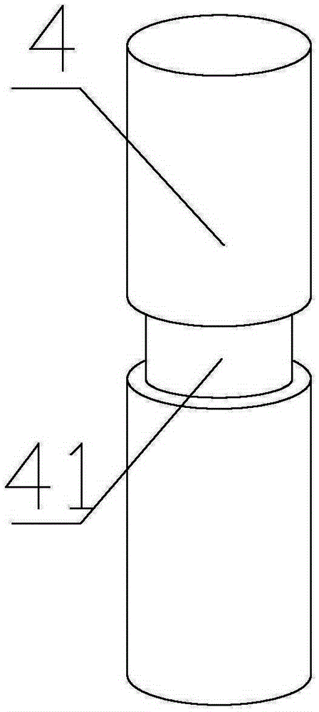
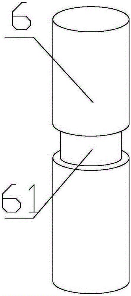
[0030] Based on the first or second embodiment, the positioning shaft 4 is provided with a positioning collar 41 ; the clamping shaft 6 is provided with a clamping collar 61 . The positioning collar 41 is set on the positioning shaft 4, which can effectively prevent the steel bar from slipping during the bending process, ensuring the bending accuracy and bending quality of the steel bar bending machine; the clamping collar 61 is provided on the clamping shaft 6, which can further Prevent the bar from slipping during bending.


PUM


Abstract

The invention discloses a steel bar bending machine and relates to the technical field of steel bar bending molding equipment. The invention aims to provide the steel bar bending machine capable of processing steel bars with different bending radii. According to the technical scheme, the steel bar bending machine comprises a working plate located at the top part of a machine body, positioning shafts and clamping shafts, wherein the working plate comprises a fixed plate and a rotating plate, the rotating plate and a driving device inside the machine body are connected and the rotating plate rotates around the axial line of the rotating plate, a plurality of positioning shaft holes and clamping shaft holes are evenly formed in the rotating plate and along the peripheral direction of the rotating plate, the positioning shaft holes form a plurality of concentric circles on the rotating plate, the positioning shafts and the clamping shafts are respectively and correspondingly placed inside the positioning shaft holes and the clamping shaft holes, a pin stopping hole is formed in the fixed plate, and a pin stopping shaft is arranged inside the pin stopping hole. The positioning shaft holes form the concentric circles on the rotating plate, the steel bars with different bending radii can be processed aiming at the positioning shaft holes of different diameters, and the application range of the steel bar bending machine is enlarged. The steel bar bending machine is suitable for serving as a steel bar bending machine.

Description

technical field [0001] The invention relates to the technical field of steel bar bending and forming equipment, in particular to a steel bar bending machine. Background technique [0002] With the gradual development of my country's economic construction, large-scale construction projects are being carried out all over the country to build various residential buildings, office buildings, road works and other projects under construction. A large number of steel bars are bent. For the bending of steel bars, the traditional method is mainly to operate manually, but manual bending of steel bars not only consumes a lot of manpower, but also takes up a lot of construction space. Therefore, in order to solve this problem, there has been a commonly used steel bar processing machine in the prior art—a steel bar bending machine. The steel bar bending machine mainly includes a fuselage and a working disc that is positioned at the top of the fuselage and can rotate around its central ax...

Claims


Application Information

Patent Timeline
Patent Type & Authority Patents(China)
IPC IPC(8): B21F1/00
CPCB21F1/008
Inventor 陈安民
Owner SICHUAN DINGRUI HYDRAULIC EQUIP MFR
Why Eureka
Try Eureka