A special rope throwing device for power transmission

A rope-throwing device and a pulling line technology, applied in the direction of overhead lines/cable equipment, etc., can solve the problems of complex structure, waste of resources, inconvenient operation, etc., and achieve the effect of simple structure, resource saving, and convenient use

Inactive Publication Date: 2017-11-17
STATE GRID CORP OF CHINA +1
View PDF7 Cites 0 Cited by
  • Summary
  • Abstract
  • Description
  • Claims
  • Application Information

AI Technical Summary

Problems solved by technology

This method is not only complicated in structure, but also wastes resources and is not easy to operate

Method used


Image

  • A special rope throwing device for power transmission

Examples


Embodiment Construction

[0015] The special rope throwing device for power transmission of the present invention will be described in detail below in conjunction with the accompanying drawings.

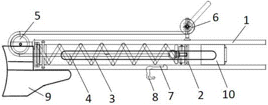
[0016] See attached figure 1 The special rope throwing device for power transmission includes a conduit 1 . The front end of the conduit 1 is open to allow a weight 10 connected to a lead wire (not shown) to be ejected therefrom. The rear end of the catheter 1 has a tail (not marked). A piston 2 is accommodated in the conduit 1 , and a spring 3 is connected between the piston 2 and the tail of the conduit 1 . When the piston 2 moves towards the tail of the catheter 1, the spring 3 is compressed. The pulling wire 4 passes through the tail of the guide tube 1 and is connected with the piston 2 , and its other end is connected with the wire tightener 6 around the pulley 5 arranged at the rear end of the guide tube 1 . Therefore, rotating the tensioner 6 pulls the piston 2 backwards through the pull wire 4, f...


PUM


Abstract

The invention provides a special rope throwing device for power transmission, which includes a conduit, the front end of which is open, and the rear end has a tail. A piston with a positioning portion is accommodated in the guide tube. An elastic element is connected between the tail of the conduit and the piston. A pulling wire passes through the tail of the catheter and is connected with the piston, and the other end of the pulling wire is connected with a tightening device through a guiding element. The guide tube is also provided with a trigger moving slot, and a trigger that can be engaged with the positioning part of the piston is movably arranged in the trigger moving slot. The special rope thrower for power transmission pulls the piston and compresses the elastic element through the traction line, without the need for external objects, which is not only convenient but also labor-saving. In addition, the trigger of the special rope thrower for power transmission can move back and forth along the trigger moving slot, so the deformation of the elastic element can be adjusted, thereby adjusting the shooting range, which is suitable for practical use.

Description

technical field [0001] The invention belongs to the technical field of installation and maintenance tools for transmission lines, and in particular relates to a tool for rope-throwing operation of high-voltage transmission lines. Background technique [0002] With the development of urban building construction and road network construction, the scale of my country's power grid continues to expand. During the construction and maintenance of transmission lines, surrounding tall trees often affect the safety of transmission lines. Therefore, these trees need to be felled. In tree felling operations, the key to ensuring the safety of electrical equipment and operators is to control the falling direction of trees. Generally, the tether method is used to control the falling direction of trees. For tall trees, in order to effectively control the trees from falling, it is necessary to tie the control rope high enough. [0003] At present, the commonly used tethering methods inclu...

Claims


Application Information

Patent Timeline
Patent Type & Authority Patents(China)
IPC IPC(8): H02G1/02
Inventor 张明李庆兴刘广州吴国军武继雷吴伟廖志斌张大车叶辉于启万周燕青孙大校李运峰饶金阁
Owner STATE GRID CORP OF CHINA
Why Eureka
Try Eureka