A cupping device that prevents falling off

A cupping device and anti-shedding technology, applied in the field of medical devices, can solve the problems of unsatisfactory use effect, shedding, discomfort of patients, etc., and achieve the effects of not easily falling off, stimulating acupoints, and promoting blood circulation.

Active Publication Date: 2016-08-24
南通江海港建设工程有限公司
View PDF8 Cites 0 Cited by
  • Summary
  • Abstract
  • Description
  • Claims
  • Application Information

AI Technical Summary

Problems solved by technology

However, the existing cupping device is prone to fall off when the negative pressure is low, and if the negative pressure is too high, the patient will feel uncomfortable and the use effect is not ideal

Method used


Image

  • A cupping device that prevents falling off
  • A cupping device that prevents falling off
  • A cupping device that prevents falling off

Examples


Embodiment 1

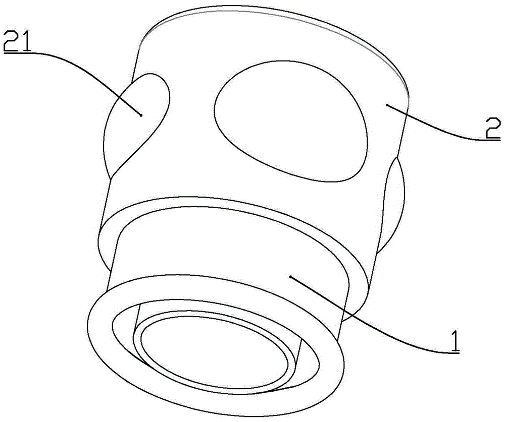
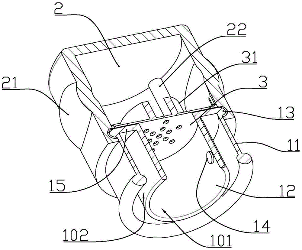
[0014] according to Figure 1 to Figure 3 As shown, the anti-falling cupping device described in this embodiment includes an integrally formed plexiglass tube body 1 and an elastic rubber bowl 2 sleeved at one end of the tube body to generate negative pressure; The plexiglass tube body comprises a circular outer tube body 11 and an inner tube body 12 coaxially arranged with the outer tube body, and one end of the inner tube body and the outer tube body is connected by an annular connecting wall 15 An annular outer cavity 102 is formed between the outer tube body and the inner tube body, and an inner cavity 101 is formed in the inner circumference of the inner tube body and the elastic rubber bowl; A one-way valve 14 that leads to the inner cavity in one direction; an outer flange 13 is formed on the outer side wall of the outer tube body adjacent to the end of the annular connecting wall, and the position of the elastic rubber bowl near the port is formed to cooperate with the...

Embodiment 2

[0019] according to figure 1 , Figure 4 As shown, the anti-falling cupping device described in this embodiment includes an integrally formed plexiglass tube body 1 and an elastic rubber bowl 2 sleeved at one end of the tube body to generate negative pressure; The plexiglass tube body comprises a circular outer tube body 11 and an inner tube body 12 coaxially arranged with the outer tube body, and one end of the inner tube body and the outer tube body is connected by an annular connecting wall 15 An annular outer cavity 102 is formed between the outer tube body and the inner tube body, and an inner cavity 101 is formed in the inner circumference of the inner tube body and the elastic rubber bowl; A one-way valve 14 that leads to the inner cavity in one direction; an outer flange 13 is formed on the outer side wall of the outer tube body adjacent to the end of the annular connecting wall, and the position of the elastic rubber bowl near the port is formed to cooperate with the...


PUM


Abstract

The invention discloses an anti-dropping cupping device, which comprises an integrally formed plexiglass tube body and an elastic rubber bowl sleeved at one end of the tube body for generating negative pressure; the plexiglass tube body includes A circular outer tube body and an inner tube body coaxially arranged with the outer tube body, one end of the inner tube body and the outer tube body are connected through an annular connecting wall; the outer tube body and the inner tube body An annular outer cavity is formed between them, and an inner cavity is formed in the inner circumference of the inner tube and the elastic rubber bowl; a one-way valve is installed on the inner tube body to conduct one-way from the outer cavity to the inner cavity; The above-mentioned elastic rubber bowl is formed with a plurality of convex walls with different thicknesses, so that when pressing different convex walls with the same range, the negative pressure generated due to the restoring force of the convex walls is different, so that it can be conveniently Obtain different negative pressure sizes, which are suitable for different acupuncture points of cupping.

Description

technical field [0001] The invention belongs to the field of medical equipment, and in particular relates to a cupping device structure for preventing falling off. Background technique [0002] Traditional cupping devices use bamboo or glass jars. When in use, put ignited alcohol cotton into the jar to increase the temperature of the air in the jar and reduce the air density, and then quickly buckle the mouth of the cupping device to the acupuncture points of the body After the temperature in the cupping device drops, negative pressure is generated to suck it tightly on the skin. Because the use of open flames will be dangerous, manufacturers have developed various cupping devices with new structures. Generally, a one-way valve leading from the inside to the outside is installed on the tank body of the cupping device, and the outside of the one-way valve can be detachably connected. An air pump, align the mouth of the cupping device with the acupoints and then operate the p...

Claims


Application Information

Patent Timeline
Patent Type & Authority Patents(China)
IPC IPC(8): A61M1/08A61H9/00
CPCA61M1/0003A61H9/0057A61H2009/0064A61M1/08A61M2205/05A61M2205/075A61M2210/04A61M1/741A61M1/82
Inventor 李为松
Owner 南通江海港建设工程有限公司
Why Eureka
Try Eureka