Broadband Piezoelectric Vibration Energy Harvesting Device with Movable Mass Ring

A technology of vibration energy collection and dynamic mass, which is applied to piezoelectric effect/electrostrictive or magnetostrictive motors, electrical components, generators/motors, etc. Increased costs and other issues

Inactive Publication Date: 2017-01-04
ANHUI UNIVERSITY
View PDF5 Cites 0 Cited by
  • Summary
  • Abstract
  • Description
  • Claims
  • Application Information

AI Technical Summary

Problems solved by technology

This needs to consume a lot of manpower and material resources, which increases the cost. Obviously, it is not advisable in reality. Moreover, if the vibration energy harvesting device is placed in an untouched place to power the sensor, broadband work cannot be achieved.

Method used


Image

  • Broadband Piezoelectric Vibration Energy Harvesting Device with Movable Mass Ring
  • Broadband Piezoelectric Vibration Energy Harvesting Device with Movable Mass Ring
  • Broadband Piezoelectric Vibration Energy Harvesting Device with Movable Mass Ring

Examples


Embodiment Construction

[0028] The following is a detailed description of the embodiments of the present invention. This embodiment is implemented on the premise of the technical solutions of the present invention, and provides detailed implementation methods and specific operation processes.

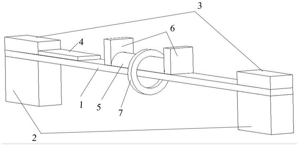
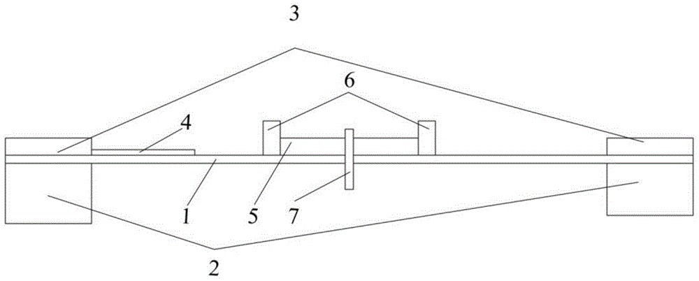
[0029] Such as figure 1 with figure 2 As shown, the structure diagram of Embodiment 1 of the vibration energy harvesting device provided by the present invention includes: elastic beam 1, support base 2, cover plate 3, piezoelectric element 4, slideway 5, limit stopper 6 and movable mass Ring 7. Among them: the two ends of the elastic beam 1 are fixed on the support base 2 by the cover plate 3, the piezoelectric element 4 is pasted on the root of the elastic beam 1, the slideway 5 is located in the middle of the elastic beam 1, and the limit block 6 is located on the slideway Both ends are fixed on the elastic beam 1, and the movable mass ring 7 passes through the slideway 5 and the elastic beam 1, and is s...


PUM


Abstract

The invention discloses a wide-band piezoelectric vibration energy collection device with a movable mass ring, comprising: an elastic beam, a piezoelectric element, a slideway, a limit block and a movable mass ring, the elastic beam is suspended in the air, Its two ends are fixed, the piezoelectric element is close to the surface of the elastic beam and close to the fixed end of the elastic beam, the slideway is located in the middle of the elastic beam, and the limit stops are located at both ends of the slideway and fixed on the elastic beam On the beam, the movable mass ring passes through the slideway and the elastic beam and hangs freely on the slideway. The device of the invention increases the frequency bandwidth of vibration energy collection by utilizing the motion behaviors such as sliding and rotation generated by the movable mass ring under the action of external vibration, and realizes the broadband operation of the piezoelectric vibration energy collection device.

Description

technical field [0001] The invention belongs to the technical field of energy and electronics, and relates to an energy collection device, in particular to a broadband piezoelectric vibration energy collection device with a movable mass ring. Background technique [0002] With the continuous development of technologies such as the Internet of Things, wireless sensor networks, and micro-electro-mechanical systems, how to efficiently power various sensors and actuators in them for a long time is becoming a major obstacle to their development. Although such devices consume less energy, they are often scattered in remote and harsh environments or implanted inside objects when used, which puts forward relatively high comprehensive requirements for the volume, cost, and lifespan of energy supply components. The main power supply methods at present are batteries and wired power supply. The traditional battery power supply method is difficult to overcome the problems of short life,...

Claims


Application Information

Patent Timeline
Patent Type & Authority Patents(China)
IPC IPC(8): H02N2/18
Inventor 王佩红刘慧婷鲁毓岚袁梅张一强孙兆奇
Owner ANHUI UNIVERSITY
Why Eureka
Try Eureka