
Cooler structure

A cooler and cooling device technology, applied in the direction of heat exchanger types, indirect heat exchangers, fixed tubular conduit components, etc., can solve the problems of cooler use restrictions, inconvenient structural coolers, etc., to improve space utilization, Excellent ventilation effect and easy operation

Inactive Publication Date: 2015-01-21
SEC ELECTRIC MACHINERY
View PDF7 Cites 3 Cited by
  • Summary
  • Abstract
  • Description
  • Claims
  • Application Information

AI Technical Summary

Problems solved by technology

[0002] In the prior art, the external air path fan of the IC666 air-to-air cooler is installed on the top surface of one side of the main body of the cooler, which is in the form of end-face hanging, which increases the total length of the cooler to a considerable extent, thus determining the installation space of the cooler. For more compact occasions, the use of coolers with this structure is greatly restricted
The situation of space constraints caused great inconvenience to the use of this structural cooler

Method used


Image

  • Cooler structure
  • Cooler structure

Examples


Embodiment Construction

[0010] The specific embodiments of the present invention will be further described below in conjunction with the accompanying drawings.

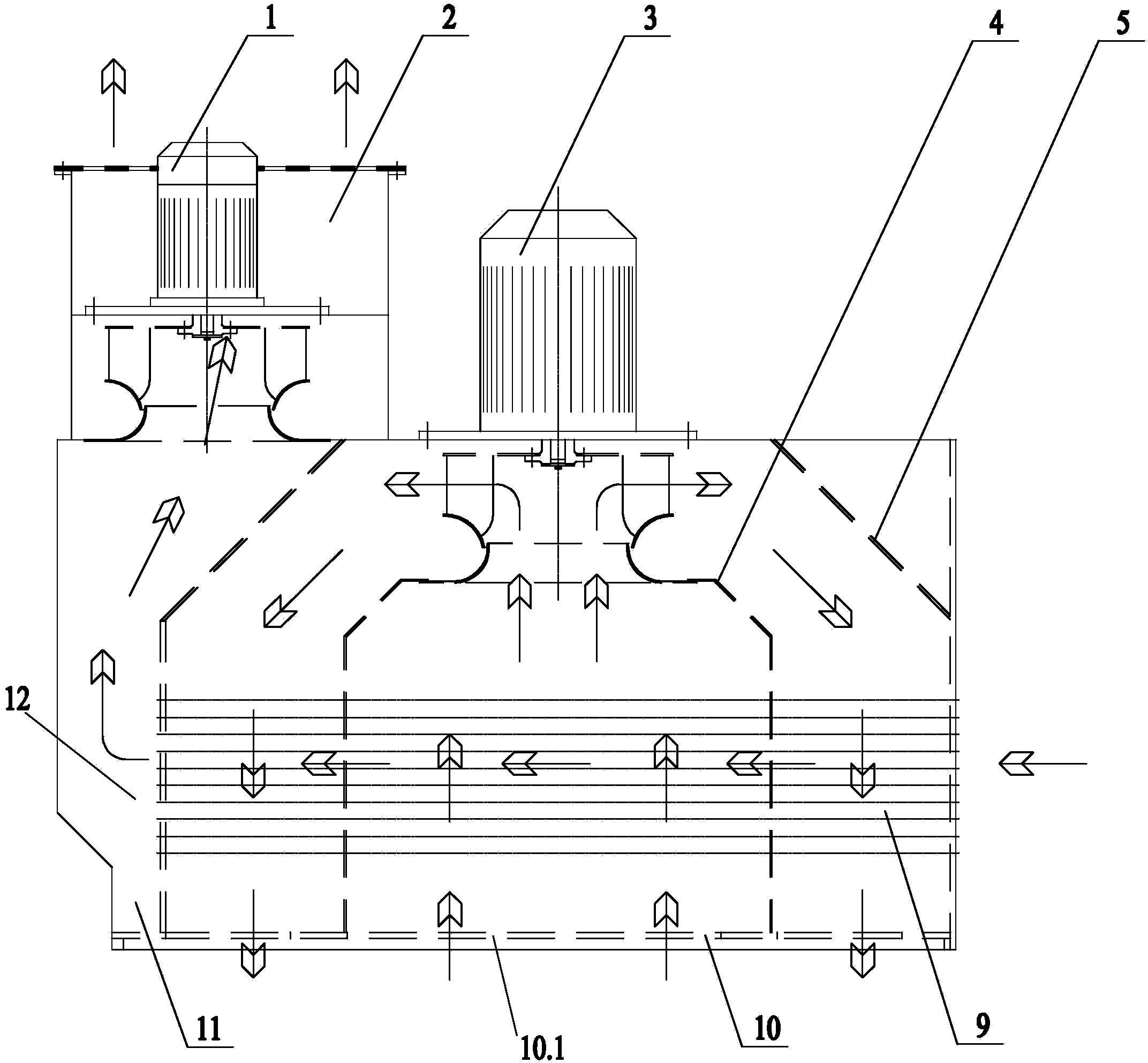
[0011] figure 1 , 2 Including the first fan 1, the air outlet cover 2, the main air outlet 2.1, the second fan 3, the curved plate 4, the first deflector 5, the second deflector 6, the mesh plate 7, the partition 8, the cooling Device 9, bottom plate 10, first air vent 10.1, fume hood 11, air outlet side 12, air inlet hole 13, etc.

[0012] Such as figure 1 As shown, the present invention is a cooler structure, comprising a fume hood 11, the bottom plate 10 of the fume hood 11 is provided with a first vent 10.1, the inside of the fume hood 11 is provided with a cooling device 9, and the air is discharged from the cooling device 9 Air inlet 13 is offered on the fume hood 11 top plate above side 12, and air outlet hood 2 is fixedly set on fume hood 11 tops, and described air outlet hood 2 wraps air inlet 13 in, and in the air outlet hood 2 ...


PUM


Abstract

The invention belongs to the technical field of heat exchange and particularly provides a cooler structure. The cooler structure comprises a ventilation cabinet, wherein a first ventilation opening is formed in a base plate of the ventilation cabinet, a cooling device is arranged in the ventilation cabinet, an air inlet hole is formed in a top plate of the ventilation cabinet above the air outlet side of the cooling device, an air outlet cover is fixedly arranged at the top of the ventilation cabinet and covers the air inlet hole, and a first fan is installed on two sides of the air outlet cover respectively, corresponding to upper portion of the air inlet hole. A main air outlet is formed in the middle position of the air outlet cover, the inner cavity of the air outlet cover is separated by a partition plate, second guide plates extending towards two sides of the length direction of the ventilation cabinet are respectively welded on two end faces of the lower portion of the partition plate, and the top face of the main air outlet is connected with a screen plate. Due to the fact that the outer-air-path fans and the ventilation cabinet are vertically installed, the length of a cooler body is decreased to a great extent, the space utilization rate of a whole cooler is improved, and the cooler structure is suitable for an occasion with a small and compact field and poor ventilation environment.

Description

technical field [0001] The invention belongs to the technical field of heat exchange, in particular to a cooler structure. Background technique [0002] In the prior art, the external air path fan of the IC666 air-to-air cooler is installed on the top surface of one side of the main body of the cooler, which is in the form of end-face hanging, which increases the total length of the cooler to a considerable extent, thus determining the installation space of the cooler. In more compact occasions, the use of coolers with this structure is largely limited. The limited space situation makes the use of this structural cooler very inconvenient. Contents of the invention [0003] Aiming at the above problems, the present invention provides a cooler structure, which can effectively improve the space utilization rate of the cooler, occupy a small space and be easy to install. [0004] According to the technical solution of the present invention: a cooler structure, it is characte...

Claims


Application Information

Patent Timeline
IPC IPC(8): F28D7/00
Inventor 朱益敏施洪谢建沈国新
Owner SEC ELECTRIC MACHINERY
Learn More