
Shuttle

A shuttle and shuttle body technology, applied in the field of shuttles, can solve the problems of personnel injury, bobbin flying out, high tension of weft yarn, etc., and achieve the effects of not being easy to fly out, improving safety performance, and simple structure

Active Publication Date: 2015-01-21
南通开元投资开发集团有限公司
View PDF6 Cites 2 Cited by
  • Summary
  • Abstract
  • Description
  • Claims
  • Application Information

AI Technical Summary

Problems solved by technology

[0002] In the prior art, ordinary shuttles are usually suitable for ordinary looms, but for heavy-duty looms, due to the high tension of the weft yarn, the bobbins often fly out, which is easy to cause personal injury

Method used


Image

  • Shuttle
  • Shuttle
  • Shuttle

Examples


Embodiment

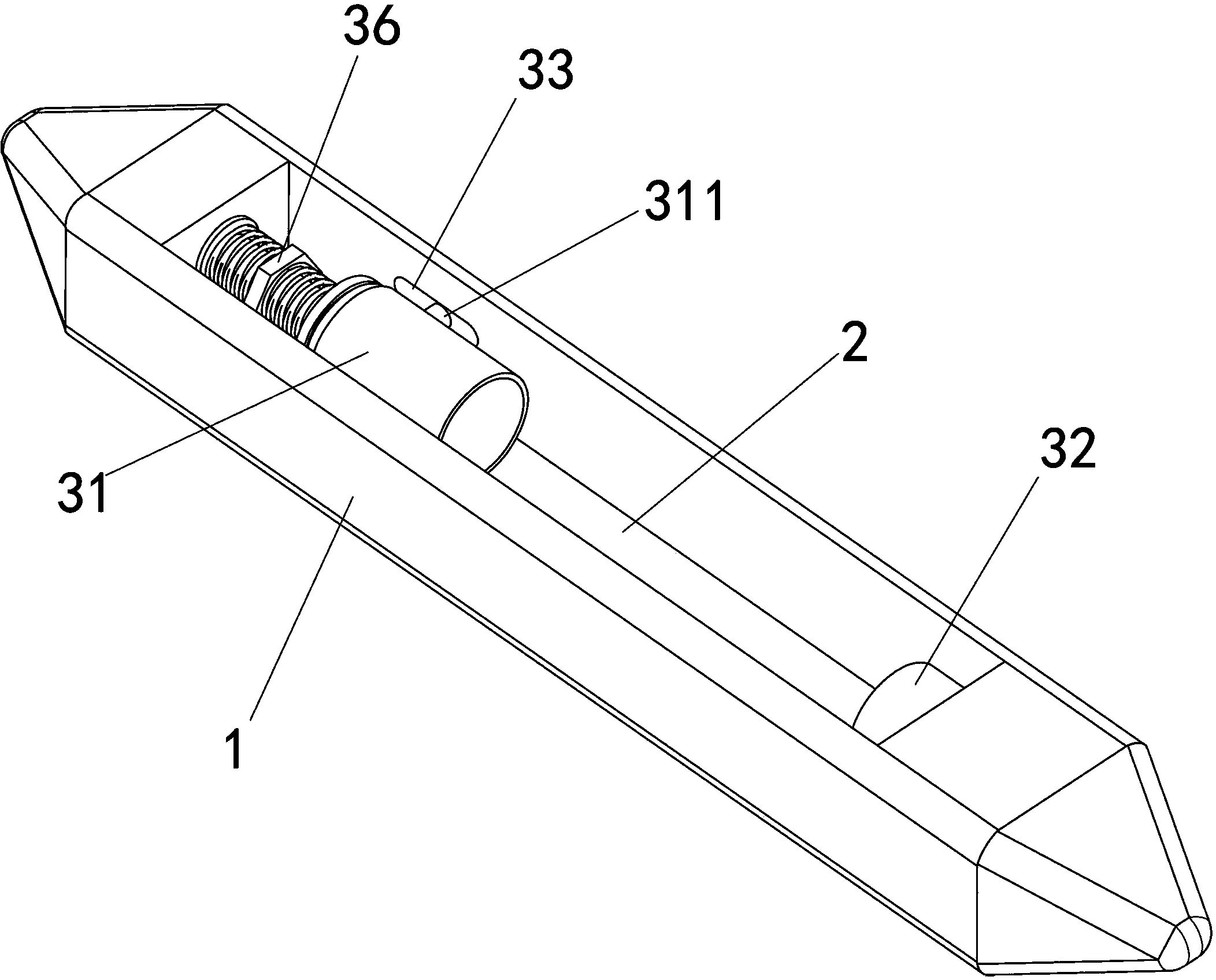
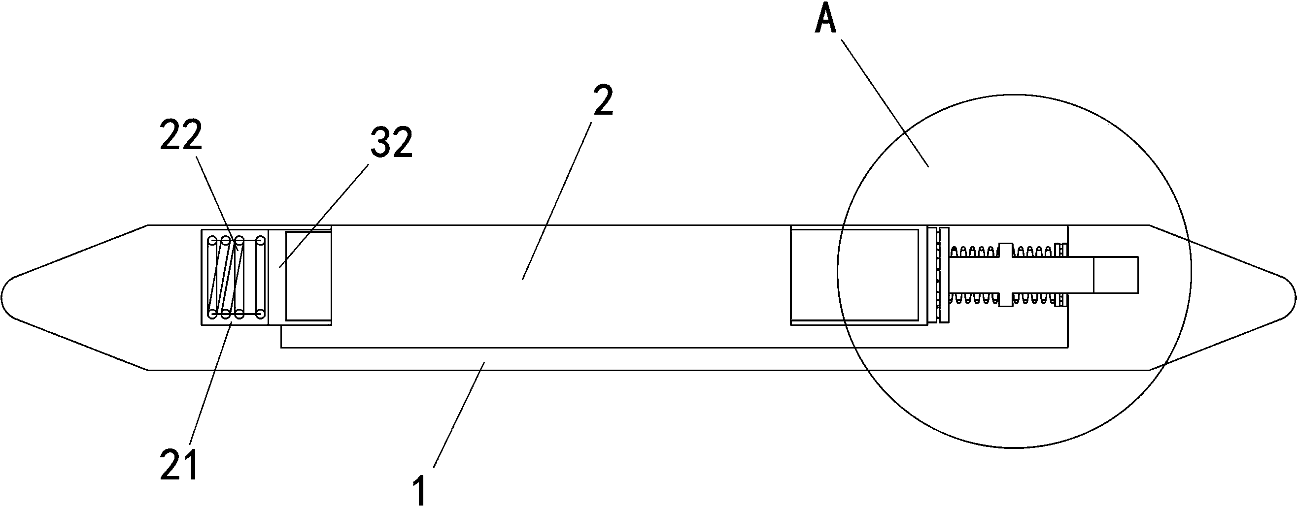
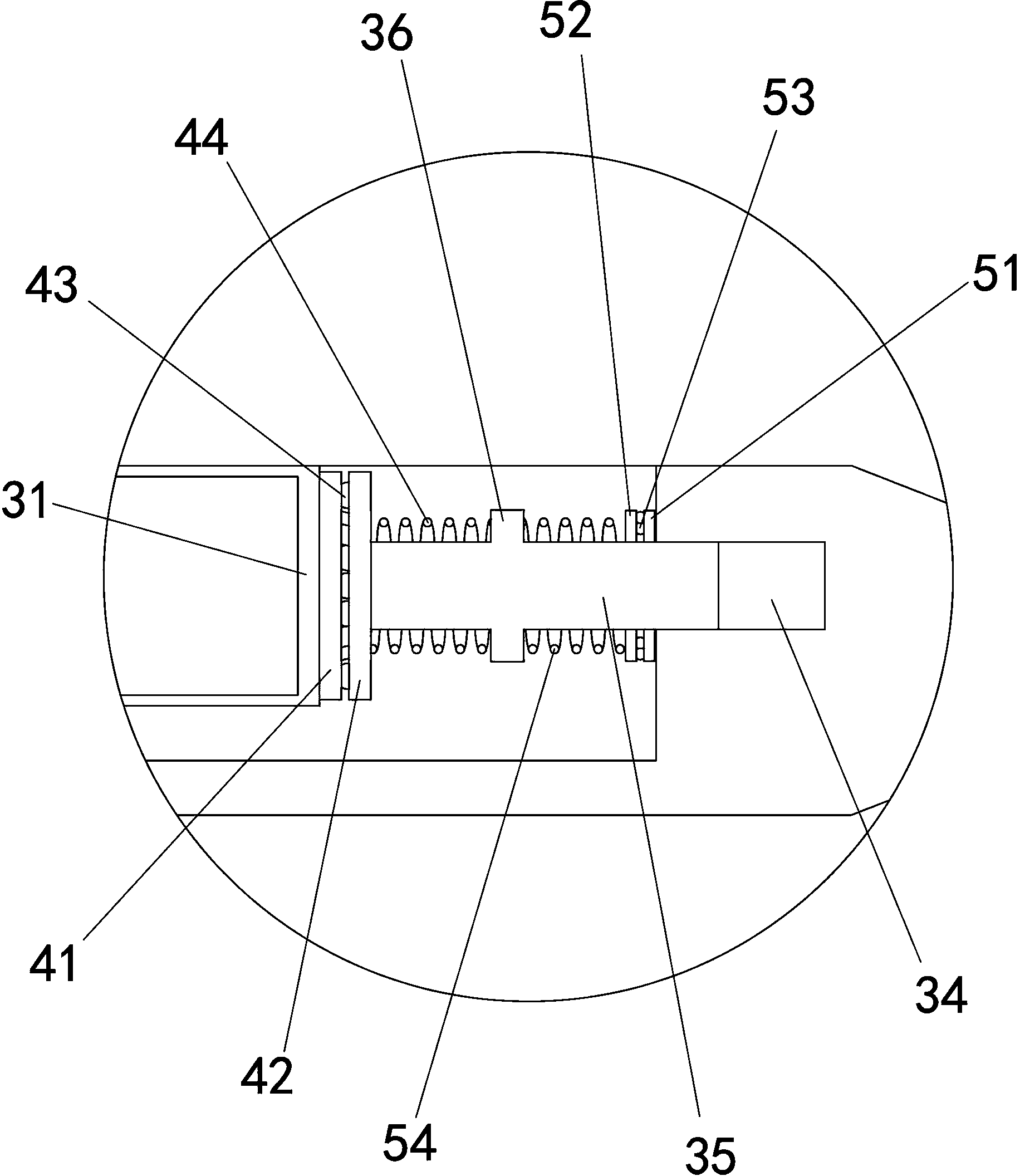
[0014] Example: such as Figure 1-3 As shown, a shuttle includes a shuttle body 1 and a bobbin installation structure arranged in a shuttle cavity 2 in the shuttle body 1 .

[0015] The bobbin installation structure includes a first sleeve 31 that is rotatably connected to the inner wall of the shuttle chamber 2 for socketing the end of the bobbin, and a second sleeve that is arranged coaxially opposite to the first sleeve 31 and telescopically arranged on the inner wall of the shuttle chamber 2. 32. A chute 33 located on the inner wall of the shuttle chamber 2 suitable for the axial sliding of the first sleeve 31. A threaded hole 34 is provided on the inner wall of the shuttle chamber 2. It is threadedly connected to the threaded hole 34 and can axially interfere with the first sleeve The screw 35 of 31 and the adjusting block 36 fixedly connected to the screw 35; both sides of the outer wall of the first casing 31 are respectively provided with rotating shafts 311 falling in...


PUM


Abstract

The invention relates to a loom in textile equipment, in particular to a shuttle. The shuttle comprises a shuttle body and a bobbin mounting structure arranged in a shuttle cavity in the shuttle; the bobbin mounting structure comprises a first sleeve, a second sleeve, sliding slots, a threaded hole, a screw and an adjusting body, wherein the first sleeve rotationally connected to the inner wall of the shuttle cavity is used for sleeving the end of a bobbin, the second sleeve is arranged with the first sleeve coaxially and oppositely and arranged to the inner wall of the shuttle cavity retractably, the sliding slots are arranged in the inner wall of the shuttle cavity and suitable for axial sliding of the first sleeve, the threaded hole is arranged in the inner cavity of the shuttle cavity, the screw is in threaded connection with the threaded hole and can axially butt against the first sleeve, and the adjusting block is fixedly connected to the screw; rotating shafts correspondingly falling into the corresponding sliding slots are arranged on two sides of the outer wall of the first sleeve respectively. The bobbin can be well stabilized, and the shuttle has good safety even if being applied to heavy looms.

Description

technical field [0001] The invention relates to a loom in textile equipment, in particular to a shuttle. Background technique [0002] In the prior art, ordinary shuttles are usually suitable for ordinary looms, but for heavy looms, because the weft yarn tension is relatively high, the bobbins often fly out, easily causing personal injury. Contents of the invention [0003] The object of the present invention is to provide a shuttle that can better stabilize the bobbin, so that it can have good safety even if it is applied to a heavy-duty loom. [0004] The above-mentioned technical purpose of the present invention is achieved by the following technical solutions: a shuttle, comprising a shuttle body, a bobbin installation structure arranged in a shuttle chamber in the shuttle body; The inner wall of the shuttle cavity is used to socket the first sleeve at the end of the bobbin, and the second sleeve is arranged coaxially opposite to the first sleeve and telescopically ar...

Claims


Application Information

Patent Timeline
Patent Type & Authority Applications(China)
IPC IPC(8): D03J5/08
CPCD03J5/08
Inventor 张晓棠
Owner 南通开元投资开发集团有限公司
Learn More