
Camera-shooting incubator

An incubator and camera technology, applied in the field of medical devices, can solve problems such as labor-intensive, difficult for babies or animal cubs' health conditions, etc.

Inactive Publication Date: 2015-01-21
吴玲玲
View PDF14 Cites 5 Cited by
  • Summary
  • Abstract
  • Description
  • Claims
  • Application Information

AI Technical Summary

Problems solved by technology

[0005] Traditionally, medical staff will regularly inspect the infants or animal cubs in the incubator to check the health status of the infants or animal cubs. cub health

Method used


Image

  • Camera-shooting incubator
  • Camera-shooting incubator
  • Camera-shooting incubator

Examples


Embodiment Construction

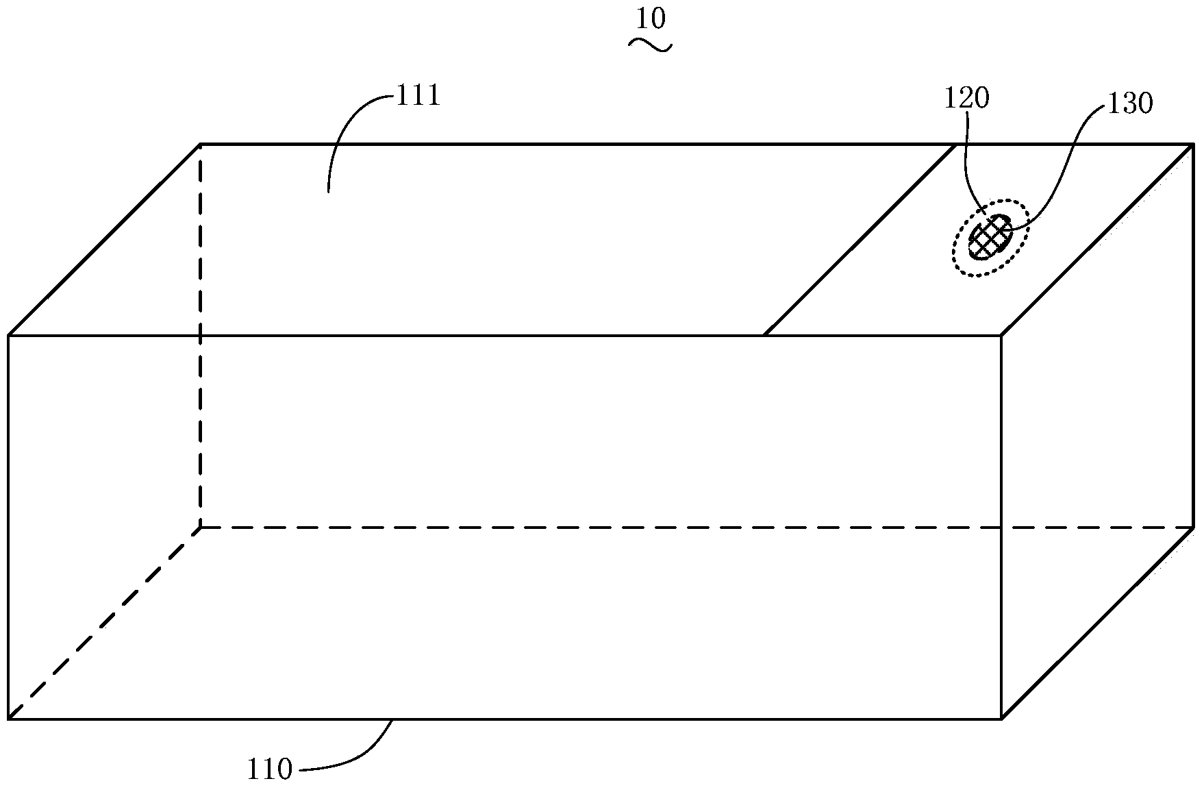
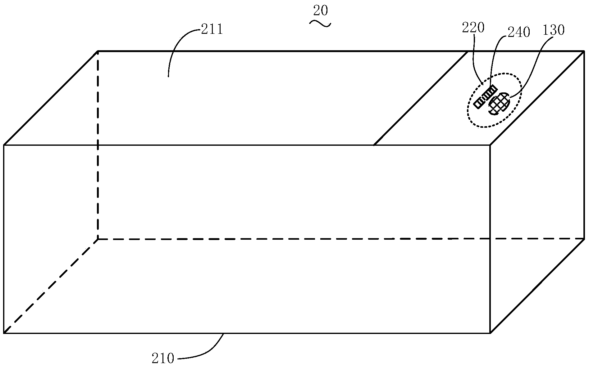
[0028] like figure 1 As shown, it is a schematic structural view of the camera incubator 10 according to a preferred embodiment of the present invention.

[0029] The camera incubator 10 includes a box body 110 , the box body 110 is provided with an installation cavity 120 , and a camera 130 is arranged in the installation cavity 120 for taking pictures of the inside of the box body 110 .

[0030] Specifically, an outlet hole 111 is opened on the upper cover of the box body 110 for putting babies or animal cubs into the box body 110 . For example, a cover plate is hinged on the edge of the outlet hole 111 for covering the outlet hole 111 to increase the airtightness of the box body 110 . The installation cavity 120 is arranged on the inside of the upper cover of the casing 110, and the camera 130 is installed in the installation cavity 120. For example, the camera 130 is an infrared camera, and is connected to an external display device. The display device can be far away fro...


PUM


Abstract

The invention relates to a camera-shooting incubator, and the incubator comprises a box; the box is provided with a mounting cavity; a camera is arranged in the mounting cavity and used to shoot the box inside. The mounting cavity of the camera-shooting incubator is provided with a camera for shooting the box inside such that video information recorded by the camera can be observed by an external display device, and the health conditions of the infant or the baby animal in the incubator can be remotely and timely mastered.

Description

technical field [0001] The invention relates to the field of medical equipment, in particular to a camera incubator. Background technique [0002] The camera incubator has a housing to provide a suitable physiological environment for an infant or young animal. In the camera incubator, the temperature, humidity, etc. in the box are controlled by the temperature, humidity and other control mechanisms arranged on the box. [0003] For example, the patent application number 200910174775 discloses a kind of incubator. In the incubator (11) according to the present invention, a single incubator (11) can be used in any state of four types of devices, so no longer It is desirable to have various types of devices. The canopy (27) is lowered and raised. In addition to this, the left and right treatment doors (22) and the foot end treatment door (23) can be located in their highest, lowest and middle positions. Additionally, the infrared heating device (28) can be lowered and raise...

Claims


Application Information

Patent Timeline
Patent Type & Authority Applications(China)
IPC IPC(8): A61G11/00A61B19/00
Inventor 吴玲玲
Owner 吴玲玲
Learn More