Pneumatic tire

一种充气轮胎、轮胎宽度方向的技术,应用在充气轮胎、轮胎零部件、轮胎胎面/胎面花纹等方向,能够解决轮胎脱离等问题,达到保证刚性、抑制排雪性能的降低、提高抗偏驶性能的效果

Active Publication Date: 2015-01-14
TOYO TIRE & RUBBER CO LTD
View PDF7 Cites 3 Cited by
  • Summary
  • Abstract
  • Description
  • Claims
  • Application Information

AI Technical Summary

Problems solved by technology

However, although it is very important to promote its detachment from the rut on the aspect of improving the anti-running performance, it is conceivable that the tires described in the above documents cannot fully exert the tires from the rut due to the location of the protrusion and the shape of the protrusion. The role of detachment

Method used


Image

  • Pneumatic tire
  • Pneumatic tire
  • Pneumatic tire

Examples


Embodiment Construction

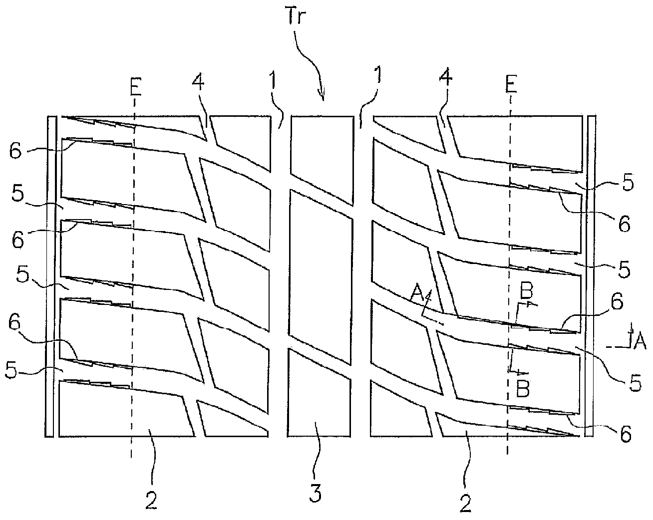
[0032] Hereinafter, embodiments of the present invention will be described with reference to the drawings.

[0033] in figure 1 The tread Tr shown is provided with: a plurality of (two in this embodiment) main grooves 1 extending along the tire circumferential direction; and a plurality of (in this embodiment) divided by these main grooves 1 There are three ground contact parts in the scheme. In this tread Tr, a block pattern is adopted, and a pair of shoulder ground contacting portions 2 located at the outermost side in the tire width direction and a central ground contacting portion 3 sandwiched by the pair of shoulder ground contacting portions 2, respectively Consists of a row of blocks. The shoulder ground contact portion 2 is provided so as to straddle the ground contact end E, and a sub groove 4 is formed closer to the inner side in the tire width direction than the ground contact end E.

[0034] The grounding end E means that the tire is installed on the standard rim spec...


PUM


Abstract

Shoulder land sections (2) which are located on the outermost portions of a tread surface in the widthwise direction of a tire comprise block rows, and shoulder lateral grooves (5) which divide the block rows extend in the widthwise direction of the tire so as to extend across ground contact ends (E). Protrusions (6) are provided on wall surfaces (5a) of each of the shoulder lateral grooves (5) so as to protrude from the wall surfaces (5a) without reaching the center of the width of the shoulder lateral groove (5). The protrusions (6) are arranged side by side in the longitudinal direction of the shoulder lateral grooves (5) in regions of the wall surfaces (5a), the regions being located on the outside of the ground contact ends (E) in the widthwise direction of the tire. The protrusions (6) have a triangular or trapezoidal shape in a plan view as well as in a front view.

Description

Technical field [0001] The invention relates to a pneumatic tire that does not impair the performance of running on snow and can improve the performance of wandering resistance Background technique [0002] For studless tires used for driving on snowy roads, a block pattern in which a plurality of blocks are arranged on the tread is generally adopted. This is to increase the pulling force (traction force) by the shearing force of the snow column at the lateral grooves dividing the blocks, and thereby improve the driving performance on snow. In addition, when driving on a snowy road, the tires fall into rut and cause the vehicle to shake, thereby prone to the so-called yaw phenomenon. Therefore, a method that can improve the yaw resistance of such tires is expected. [0003] Patent Documents 1-4 describe a pneumatic tire in which the outermost shoulder ground contact portion in the tire width direction of the tread is composed of a block row, and the tire is used to divide the bloc...

Claims


Application Information

Patent Timeline
Patent Type & Authority Applications(China)
IPC IPC(8): B60C11/11B60C11/04B60C11/13
CPCB60C11/13B60C2011/1338B60C2011/1361B60C11/01B60C11/11B60C2011/0358B60C5/00B60C11/0316B60C11/1307
Inventor 安永智一
Owner TOYO TIRE & RUBBER CO LTD
Why Eureka
Try Eureka