
Buckling and tripping device for automatic transfer switching equipment

A technology of automatic transfer switch and tripping device, applied in the direction of electric switches, circuits, electrical components, etc., can solve the problems of high switch manufacturing cost, difficult equipment, low reliability, etc., and achieve reliable closing operation and movement trajectory Simple and clear effects with a wide range of applications

Active Publication Date: 2015-01-14
WUXI HANKWANG ELECTRIC
View PDF5 Cites 1 Cited by
  • Summary
  • Abstract
  • Description
  • Claims
  • Application Information

AI Technical Summary

Problems solved by technology

[0003] At present, most of the general-purpose automatic transfer switches use V-shaped mechanisms to achieve mechanical self-locking of the reversing parts. In terms of structure, special locking electromagnets and complex locking mechanisms are required.
The existing problems of the current automatic transfer switch are: 1), the mechanism is complicated, the equipment is difficult, and the reliability is low; 2), the switch parts are many, occupying a large space; 3), the action sequence of the mechanism needs to be controlled by corresponding electronic components, The opening and closing speed is slow, 4), the switch manufacturing cost is too high, not enough energy saving and environmental protection

Method used


Image

  • Buckling and tripping device for automatic transfer switching equipment
  • Buckling and tripping device for automatic transfer switching equipment
  • Buckling and tripping device for automatic transfer switching equipment

Examples


Embodiment Construction

[0023] The present invention will be further described below in conjunction with specific drawings and embodiments.

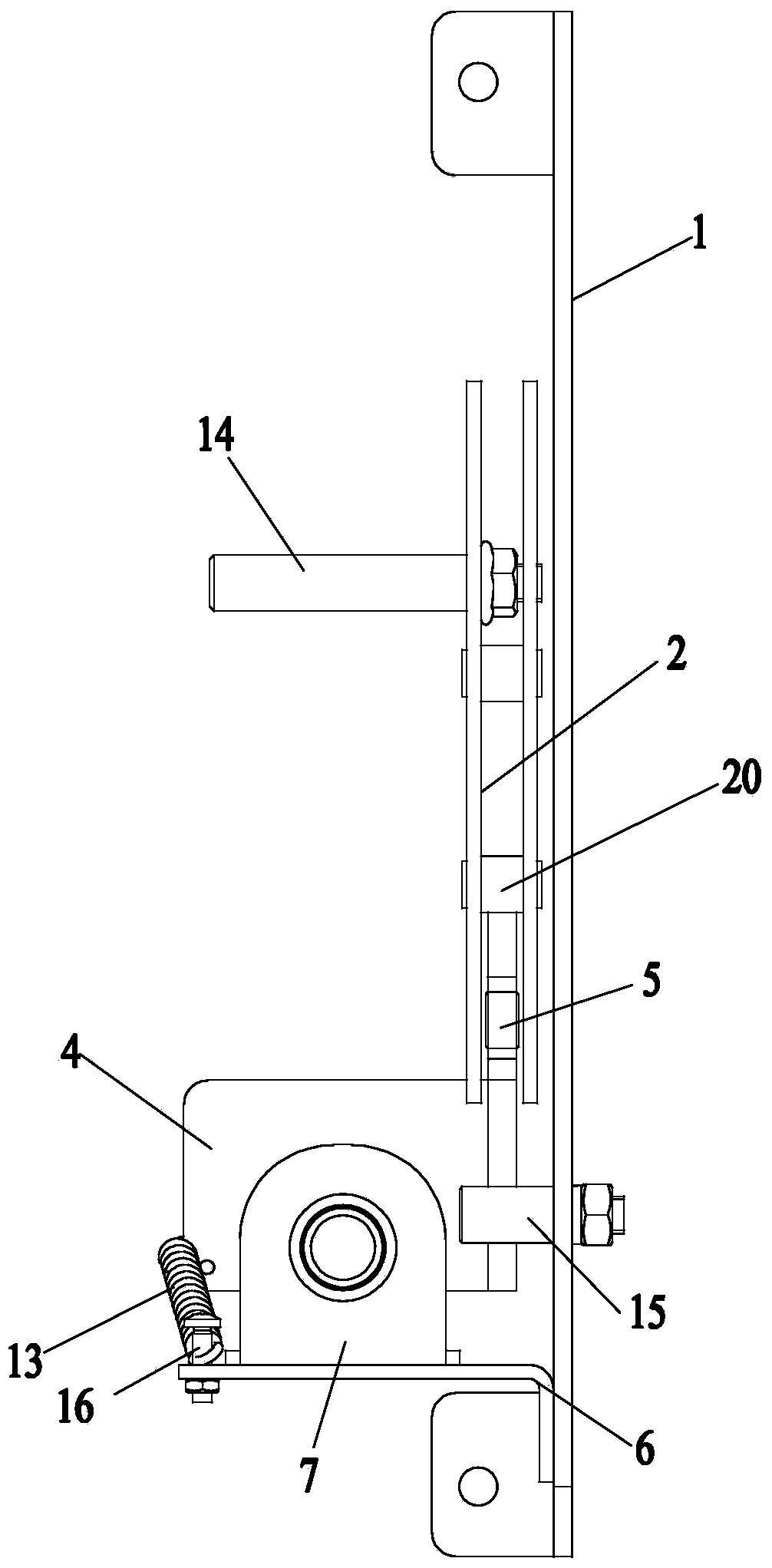
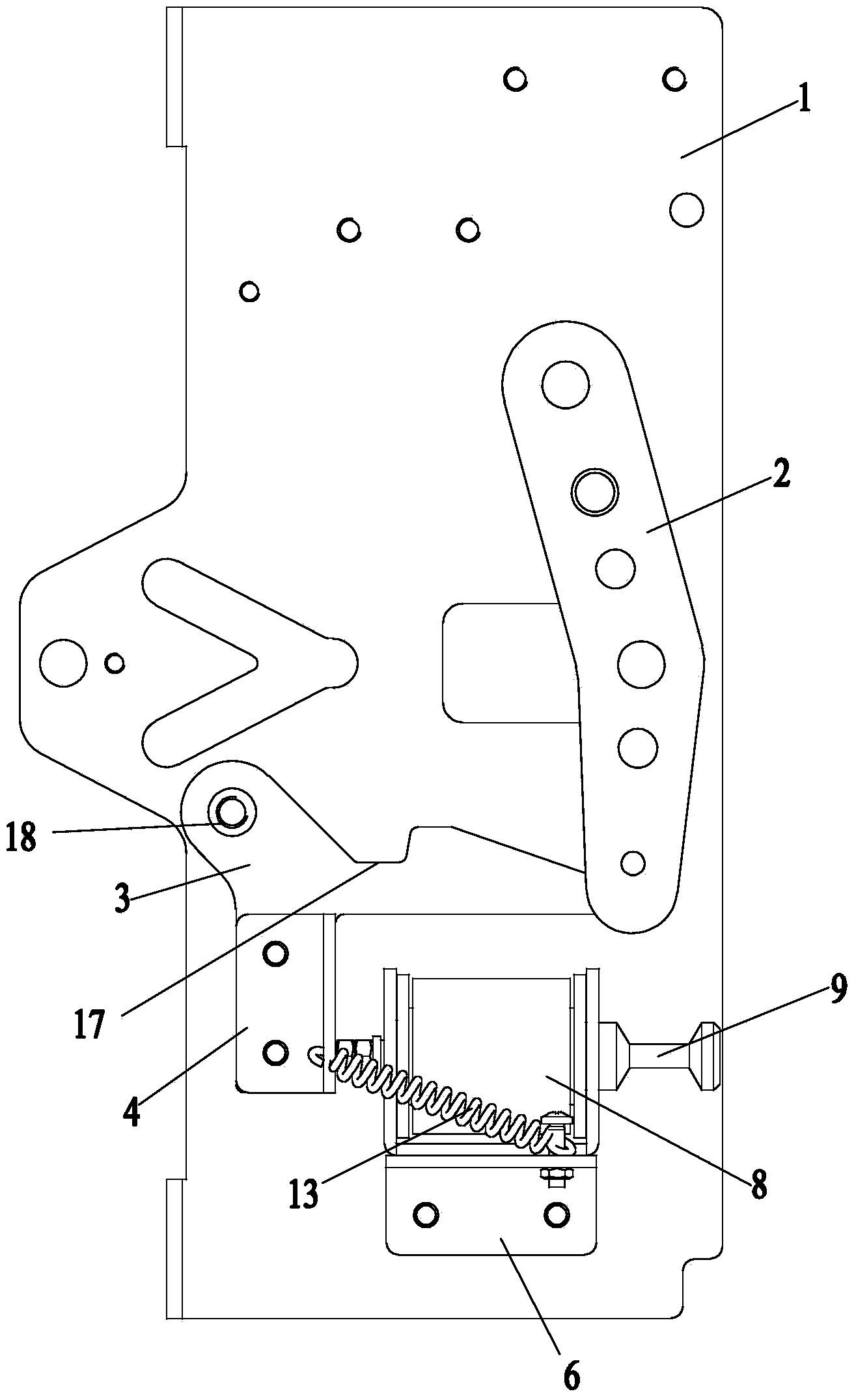
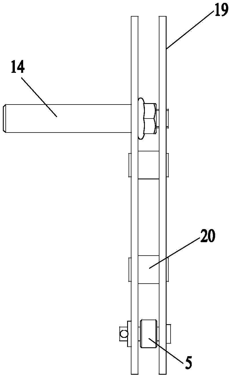
[0024] Such as figure 1 and figure 2 As shown: In order to improve the breaking performance of automatic transfer switch appliances and ensure the reliability of opening and closing of automatic transfer switches, the present invention includes a substrate 1, on which a lock for controlling the closing of automatic transfer switches is installed mechanism and a tripping mechanism for controlling the opening of the automatic transfer switch; the locking mechanism includes a lever plate body 2 and a locking plate 3, the lever plate body 2 and the locking plate 3 are hinged on the base plate 1, and the locking mechanism The plate 3 is located at one end of the lever plate body 2, and the lever plate body 2 is provided with a roller 5 that can roll on the lock plate 3 and can be embedded in the lock groove 17 on the lock plate 3, and the lever plate body 2 Rotat...


PUM


Abstract

The invention relates to a buckling and tripping device for automatic transfer switching equipment. The buckling and tripping device comprises a base plate, wherein a buckling mechanism and a tripping mechanism. The buckling mechanism comprises a lever plate body and a buckling plate, wherein the lever plate body and the buckling plate are hinged to the base plate, the buckling plate is located at one end of the lever plate body, a roller capable of rolling on the buckling plate and being embedded into a buckling groove formed in the buckling plate is arranged in the lever plate body and the lever plate body rotates on the base plate to enable the roller to be embedded into the buckling groove so as to achieve switching-on control of an automatic transfer switch. The tripping mechanism comprises a connecting plate installed on the buckling plate and a tripping action mechanism, wherein the tripping action mechanism enables the roller to break away from the buckling groove in the buckling plate through the connecting plate so as to achieve switching-off control of the automatic transfer switch. The buckling and tripping device is simple and compact in structure and capable of achieving remote operation on the automatic transfer switch, improving the on-off performance of the automatic transfer switching equipment and ensuring the switching-on and switching-off reliability of the automatic transfer switch.

Description

technical field [0001] The invention relates to a lock and trip device, especially a lock and trip device for an automatic transfer switch appliance, specifically a lock and trip device for ensuring reliable opening and closing of an automatic transfer switch appliance, belonging to The technical field of low-voltage switchgear. Background technique [0002] In the low-voltage power distribution system, the automatic transfer switching device has become an indispensable and important part for monitoring the power circuit. In the event of a power failure, one or several load circuits can be automatically switched from the failed power supply to the backup power supply to ensure continuous power supply for important loads. The simpler the operation structure of the automatic transfer switch, the higher the operational reliability of the automatic transfer switch. The locking device of the operating mechanism must be able to ensure the overtravel and final pressure of the con...

Claims


Application Information

Patent Timeline
Patent Type & Authority Applications(China)
IPC IPC(8): H01H9/20H01H3/32
CPCH01H3/46H01H9/20
Inventor 王军韦柳军杨海军石崇祯安建珍管柯茅云钱晖
Owner WUXI HANKWANG ELECTRIC
Learn More