A mechanical drafting device for an air-jet loom

A technology of drafting device and air-jet loom, which is applied to looms, textiles, textiles and papermaking, etc., can solve the problems of wasting air, large drafting air pressure, and increased costs, so as to improve quality, enhance variety adaptability, Avoid the effect of weft shrinkage

Active Publication Date: 2015-12-02
QINGDAO TIANYI GROUP RED FLAG TEXTILE MACHINERY
View PDF5 Cites 0 Cited by
  • Summary
  • Abstract
  • Description
  • Claims
  • Application Information

AI Technical Summary

Problems solved by technology

The existing solution is to install a drafting nozzle at the end of the weft insertion of the loom. The drafting nozzle is provided with an air source by an independent air bag, and a larger air pressure is used to give a drafting force to the flying weft yarn to ensure that the weft yarn It can straighten smoothly and prevent weft shrinkage. This method requires a lot of drafting air pressure, which is a serious waste of air. In addition, this process requires a special solenoid valve and drafting air bag to control the air pressure, which increases the cost, especially for Energy-saving air jets are not suitable for independent air supply looms

Method used


Image

  • A mechanical drafting device for an air-jet loom
  • A mechanical drafting device for an air-jet loom
  • A mechanical drafting device for an air-jet loom

Examples


Embodiment Construction

[0022] The present invention will be further described in detail below in conjunction with the accompanying drawings and specific embodiments, but the present invention is not limited to these embodiments.

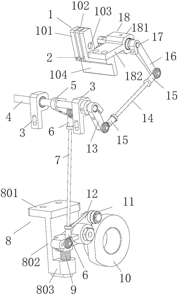
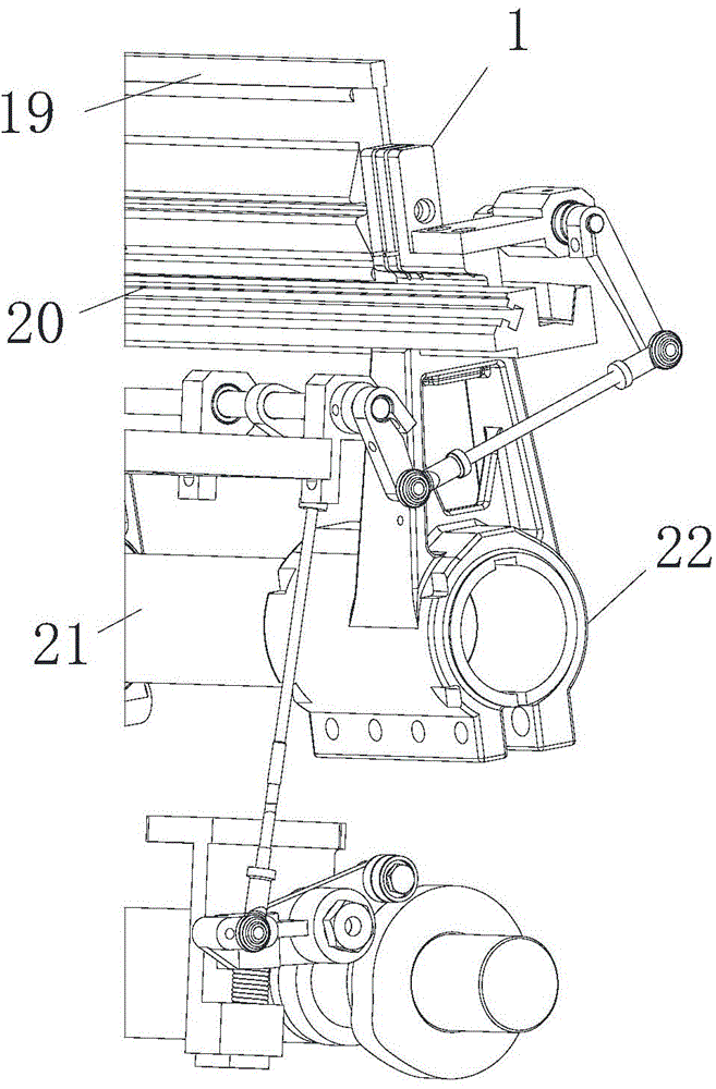
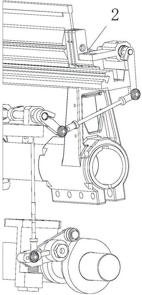
[0023] Such as figure 1 and image 3 Shown, a kind of air-jet loom mechanical drafting device comprises a loom frame, and a weft beating mechanism, a yarn clamping mechanism and a driving mechanism are arranged on the loom frame; the weft beating mechanism includes a beating shaft 21, a beating arm 22. The sley 20 and the steel reed 19, the beat-up arm 22 swings under the drive of the beat-up shaft 21, the sley 20 is fixed above the beat-up arm 22, and the steel reed 19 is arranged above the sley 20; The yarn gripping mechanism includes a yarn gripper 1 and a swing lever 2. The yarn gripper 1 includes a yarn gripper 104 and a plurality of yarn grippers 101 arranged on the yarn gripper 104 and arranged in sequence. The yarn gripper 104 is arranged on the sley 20, each yar...


PUM


Abstract

The invention discloses a mechanical drafting device of an air jet loom. The mechanical drafting device comprises a loom frame, and the loom frame is provided with a beating-up mechanism, a yarn gripping mechanism and a driving mechanism. The beating-up mechanism comprises a beating-up shaft, a beating-up support arm, a batten and a reed. The yarn gripping mechanism comprises a yarn gripper and swing rods, wherein the yarn gripper comprises a yarn gripping base and a plurality of yarn gripping pieces arranged on a yarn gripping seat and uniformly distributed; the yarn gripping seat is arranged on the reed, the relative positions of the yarn gripping pieces are provided with yarn guide holes, the yarn guide holes rightly face weft guide reed slots of the reed, a yarn gripping slot is fittingly formed between every two adjacent yarn gripping pieces, the number of the swing rods is equal to that of the yarn gripping slots, the heads of the swing rods penetrate into the yarn gripping slots, the tails of the swing rods are fixedly arranged on swing rod shafts, the swing rod shafts are hinged to a swing rod support, the swing rod support is arranged on the yarn gripping seat, the swing rod shafts are connected with the driving mechanism via a connecting rod mechanism, and the swing rods can swing up and down under drive of the reed and the swing rod shafts. The mechanical drafting device is capable of instantly gripping yarns at high speed, and looped wefts are avoided.

Description

technical field [0001] The invention belongs to the field of textile machinery, in particular to a mechanical drafting device for an air-jet loom. Background technique [0002] Stretch yarn is mainly elastic and belongs to a kind of textured yarn. Its characteristic is that the yarn can spring back quickly after being stretched. When the loom is weaving the elastic yarn weft, due to the high elasticity of the elastic yarn, weft shrinkage is prone to occur at the right side of the selvage. Therefore, in order to avoid the rebound of the weft yarn at the end of weft insertion, a drafting force is required to straighten it, and when the drafting force cannot reach the force required by the elastic yarn, weft shrinkage is prone to occur. The existing solution is to install a drafting nozzle at the end of the weft insertion of the loom. The drafting nozzle is provided with an air source by an independent air bag, and a larger air pressure is used to give a drafting force to the ...

Claims


Application Information

Patent Timeline
Patent Type & Authority Patents(China)
IPC IPC(8): D03D47/30D03D49/60
CPCD03D47/308D03D49/60
Inventor 高玉刚刘培德范龙霄逄浩然纪竹青
Owner QINGDAO TIANYI GROUP RED FLAG TEXTILE MACHINERY
Why Eureka
Try Eureka