Novel compaction platform

A vibrating table, a new type of technology, applied in the direction of molding table, molding machine, casting molding equipment, etc.

Inactive Publication Date: 2015-01-07
杨配媛
View PDF0 Cites 2 Cited by
  • Summary
  • Abstract
  • Description
  • Claims
  • Application Information

AI Technical Summary

Problems solved by technology

At present, the V-method molding line mostly adopts the form of vibrating trolley shuttle back and forth, and the molding efficiency is very low.
Vibration trolley is not suitable for automatic molding line

Method used


Image

  • Novel compaction platform
  • Novel compaction platform

Examples


Embodiment Construction

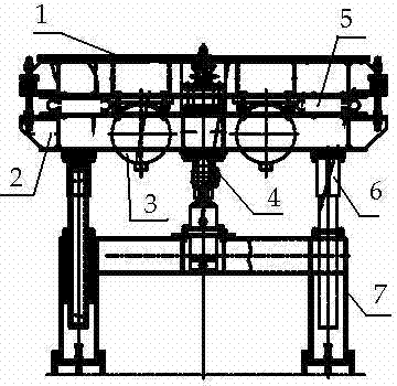
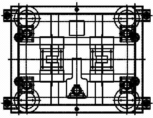
[0011] see figure 1 and figure 2 As shown, the present invention includes a body 7, a vibrating platform 1, a lifting platform 2 and a guide rod 6. The vibrating platform 1 is arranged on the top of the body 7, and a lifting platform 2 is provided below the vibrating platform 1. The lifting platform 2 is supported by the guide rods 6 , an air spring 5 and a vibrating motor 3 are respectively arranged between the lifting platform 2 and the vibrating table 1 , and a hydraulic cylinder 4 is arranged between the guiding rods 6 . The working principle is: when the formwork and the sand box are transported to the bottom of the sand warehouse through the roller table and sand needs to be added, the hydraulic cylinder 4 will lift the lifting table 2 until the vibration table 1 lifts the formwork and the sand box. At this time, the formwork and sand The box has been separated from the roller surface and is directly below the sand adding device. The air spring 5 lifts the vibrati...


PUM


Abstract

The invention relates to a novel compaction platform which comprises a machine body, a compaction platform surface, a lifting platform and guide rods, wherein the compaction platform surface is arranged at the upper part of the machine body, a lifting platform body is arranged below the compaction platform surface and is supported by the guide rods, air springs and compaction motors are respectively arranged between the lifting platform and the compaction platform surface, and a hydraulic cylinder is arranged between the guide rods. According to the novel compaction platform, a mould plate and a sand box are favorably conveyed in an automatic molding ring, and thus the modeling efficiency is greatly improved; meanwhile, because the novel compaction platform is jacked, the sealing, sand feeding and compaction of sand boxes with different heights can be realized.

Description

technical field [0001] The invention belongs to the technical field of mechanical manufacturing, and in particular relates to a novel vibrating table. Background technique [0002] In the foundry industry, V-method molding adopts dry sand molding, known as "green casting", and has been accepted by more and more enterprises in recent years. Vibration compaction can make the sand mold get better bulk density. At present, the V-method molding line mostly adopts the form of vibrating trolley shuttle back and forth, and the molding efficiency is very low. Vibrating trolleys are not suitable for automatic molding lines. Contents of the invention [0003] The present invention overcomes the deficiencies of the prior art, and proposes a new type of vibrating table, which is beneficial to the operation of the automatic molding ring, greatly improves the molding efficiency, and can realize different heights of sand due to the use of hydraulic cylinder jacking Sand and vibrate th...

Claims


Application Information

Patent Timeline
Patent Type & Authority Applications(China)
IPC IPC(8): B22C15/16B22C19/02
CPCB22C15/16B22C19/02
Inventor 杨配媛
Owner 杨配媛
Why Eureka
Try Eureka