
On-load tap changer

A technology of on-load tap-changing and switching, which is applied in the direction of electric switches, electric selector switches, inductors, etc., which can solve the problems of large installation space and achieve the effect of simple installation

Active Publication Date: 2014-12-24
MASCHFAB REINHAUSEN GEBR SCHEUBECK GMBH & CO KG
View PDF13 Cites 13 Cited by
  • Summary
  • Abstract
  • Description
  • Claims
  • Application Information

AI Technical Summary

Problems solved by technology

This complex conversion from rotary motion to translational motion and back to rotary motion again requires a large installation space for the energy storage structure in the on-load tap-changer and also requires many complex individual components

Method used


Image

  • On-load tap changer
  • On-load tap changer
  • On-load tap changer

Examples


Embodiment Construction

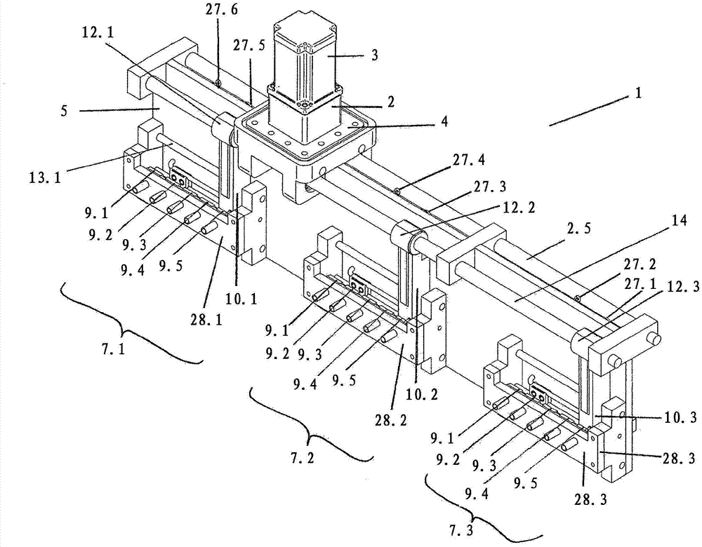
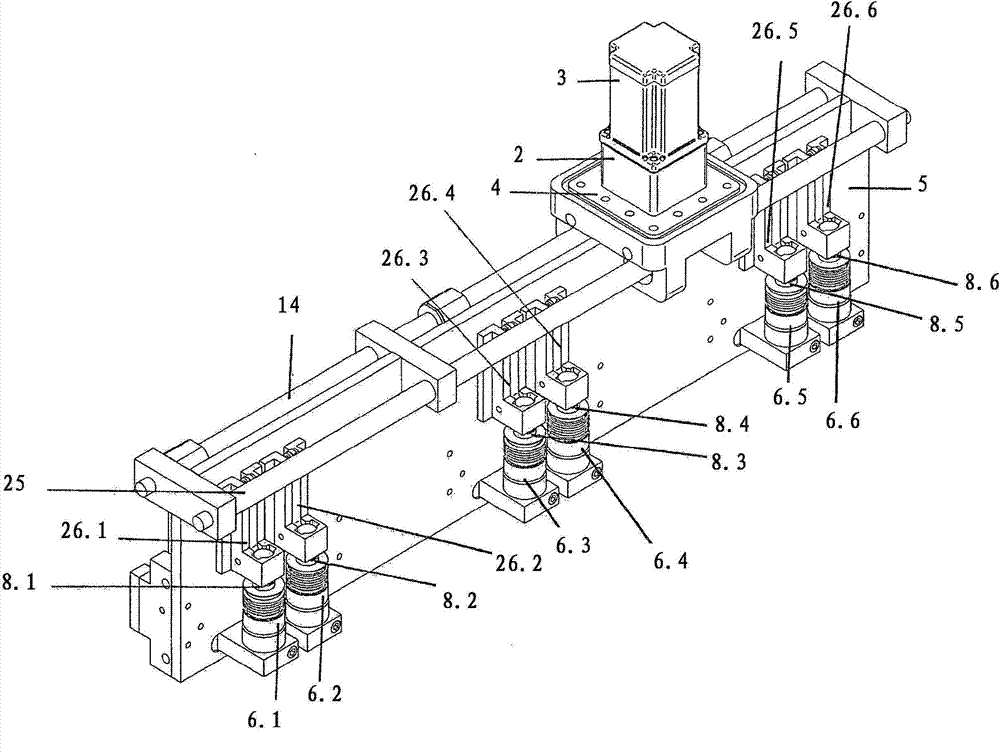
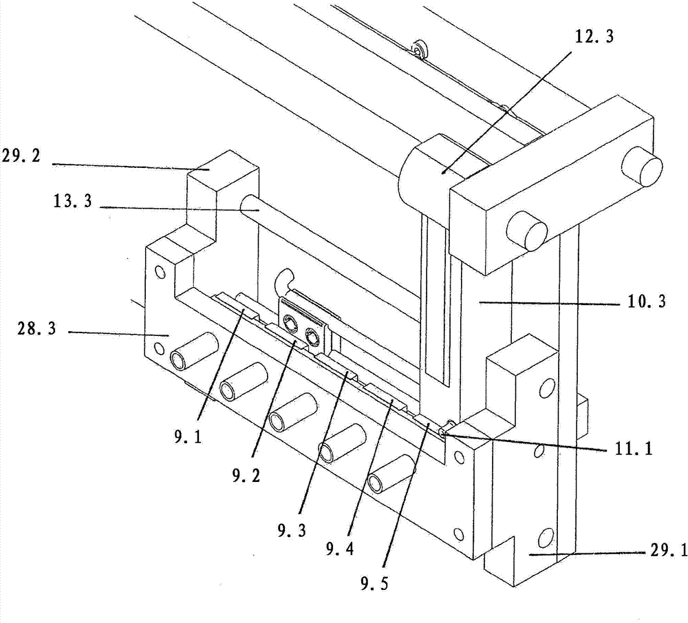
[0021] exist figure 1 and 2 2 shows an on-load tap-changer 1 according to the invention in two different perspective views, which is arranged directly below the likewise not shown transformer housing of a step-change transformer, not shown in detail. A more detailed description of the individual components of the on-load tap changer 1 and their functions follows from the following description of the figures. Such step-tunable transformers, which are sufficiently known from the prior art, comprise a transformer tank filled with insulating oil, in which at least one winding is arranged on an iron yoke. The winding is composed of a main winding and an adjusting winding, and a plurality of winding taps are arranged on the adjusting winding, and the winding taps form an adjusting range. Furthermore, the on-load tap-changer 1 comprises a drive module 2 fastened on the underside of the transformer housing, which interacts with a motor drive 3 arranged on the opposite outer side of ...


PUM


Abstract

The invention relates to an on-load tap changer for switching among different winding taps of a step transformer without interruption according to the preamble of the first patent claim. The general inventive concept lies in actuating both the selector contact unit and the switching means for uninterrupted load switching by means of a common motor drive without an energy store being connected therebetween.

Description

technical field [0001] The invention relates to an on-load tap changer according to the preamble of claim 1 for switching without interruption between different winding taps of a step-variable transformer. Background technique [0002] For many years, a large number of on-load tap-changers have been used all over the world to switch between different winding taps of step-change transformers without interruption. So-called reactor switches, which are especially common in North America, have a switching reactance which allows slow continuous switching. On-load tap-changers based on the resistance fast switching principle usually comprise a selector for power-free selection of the corresponding winding tap of the step-change transformer to which the tap should be switched and for actually switching from the current winding tap to the new, On-load changeover switch for preselected winding taps. For this purpose, diverter switches usually have switching contacts and resistive c...

Claims


Application Information

Patent Timeline
Patent Type & Authority Applications(China)
IPC IPC(8): H01H9/00
CPCH01H9/0027H01H9/0038H01F29/04H01H3/40H01H3/42H01H9/0016H01H2231/052
Inventor A·比林格尔C·哈默R·施特伦佩尔
Owner MASCHFAB REINHAUSEN GEBR SCHEUBECK GMBH & CO KG
Learn More