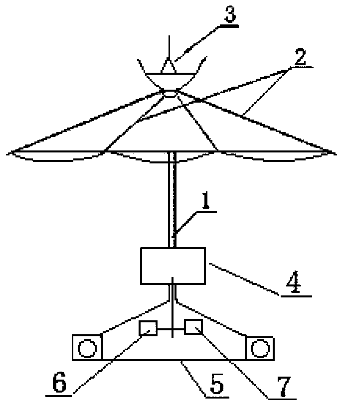
Umbrella-shaped television antenna structure
A TV antenna and umbrella-shaped technology, which is applied in the field of TV antennas, can solve the problems of passive use, the antenna has no beautifying and decorative effect, etc., and achieves the effect of good use effect.
Inactive Publication Date: 2014-12-24
曹尚运
View PDF0 Cites 0 Cited by
- Summary
- Abstract
- Description
- Claims
- Application Information
AI Technical Summary
Problems solved by technology
[0002] So far, TV antennas have various shapes, most of which are composed of two retractable metal rods. Although the effect of TV antennas is acceptable, such antennas have no beautifying and decorative functions, so it is easy to cause passive use.
Method used
View moreImage
Smart ImageViewing Examples
Examples
Embodiment Construction
[0010] The umbrella-shaped TV antenna structure has an umbrella frame column (1), an umbrella frame (2) is connected to the upper end of the umbrella frame column (1), and a signal receiver (3) is installed on the umbrella frame (2); The lower end of 1) is connected with a signal amplifier (4) and a fixing frame (5), and a U-band (6) and a V-band (7) are respectively arranged in the cavity of the fixing frame (5).
Login to View More PUM
 Abstract
The invention discloses an umbrella-shaped television antenna structure. An umbrella skeleton is connected to the upper end of an umbrella rib stand column, and a signal receiver is installed on the umbrella skeleton. A signal amplifier and a fixing frame are connected to the lower end of the umbrella rib stand column, and a U wave band and a V wave band are respectively arranged inside an inner cavity of the fixing frame. The umbrella-shaped television antenna structure can be used as a television antenna and has beatifying and decorating effects of an umbrella, and therefore the using effect is good.
Description
technical field [0001] The invention relates to a television antenna structure, in particular to an umbrella-shaped television antenna structure, which belongs to the technical field of television antennas. Background technique [0002] So far, TV antennas have various shapes, most of which are composed of two retractable metal rods. Although the effect of TV antennas is acceptable, such antennas have no beautifying and decorative functions, so it is easy to bring passive use. . Contents of the invention [0003] The purpose of the present invention is to provide a new umbrella-shaped TV antenna structure, which can improve the existing problems of the current antenna, thereby bringing convenience in use. [0004] The technical solution adopted by the present invention to solve its technical problems is: a kind of umbrella-shaped TV antenna structure, which is made up of umbrella frame column, umbrella frame, signal receiver, signal amplifier, fixed mount, U band, V band,...
Claims
Login to View More Application Information
Patent Timeline
 Patent Type & Authority Applications(China)
IPC IPC(8): H01Q1/36H01Q21/30
Inventor 曹尚运
Owner 曹尚运
Features
- R&D
- Intellectual Property
- Life Sciences
- Materials
- Tech Scout
- Unparalleled Data Quality
- Higher Quality Content
- 60% Fewer Hallucinations
Learn More Browse by: Latest US Patents, China's latest patents, Technical Efficacy Thesaurus, Application Domain, Technology Topic, Popular Technical Reports.
© 2025 PatSnap. All rights reserved.Legal|Privacy policy|Modern Slavery Act Transparency Statement|Sitemap|About US| Contact US: help@patsnap.com

