
Optical-cable cross-connecting box door lock system

A technology of optical cable transfer box and door lock, which is applied in the field of optical cable communication equipment, can solve problems such as inconvenient use and unsafety, and achieve the effect of ensuring safety, simple structure, and ensuring the safety of unlocking

Active Publication Date: 2014-12-17
北京立成通科技有限公司
View PDF6 Cites 6 Cited by
  • Summary
  • Abstract
  • Description
  • Claims
  • Application Information

AI Technical Summary

Problems solved by technology

[0005] In order to solve the disadvantages of unsafe and inconvenient use of the existing optical cable transfer box locks mentioned above, the present invention provides a door lock system for optical cable transfer box, which can be unlocked remotely or at a short distance; by setting double unlocking information Verification steps to ensure the safety of the cable transfer box

Method used


Image

  • Optical-cable cross-connecting box door lock system
  • Optical-cable cross-connecting box door lock system
  • Optical-cable cross-connecting box door lock system

Examples


specific Embodiment 1

[0042] A door lock system for an optical cable transfer box, the working method of which is as follows:

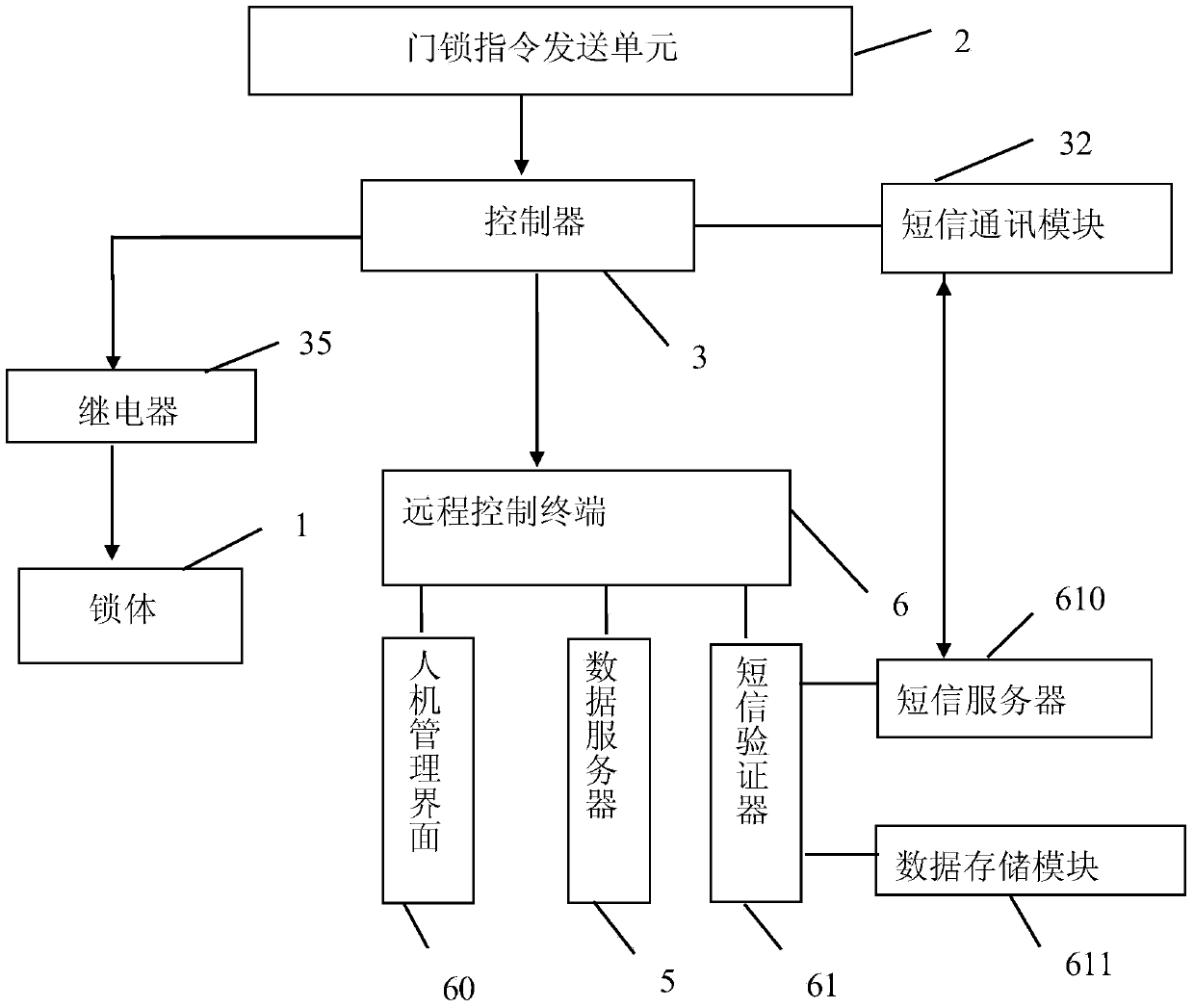
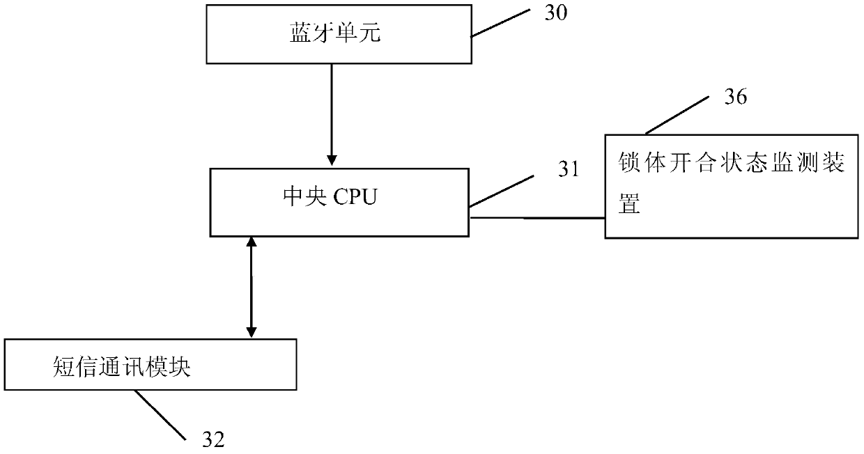
[0043] S1, the user sends the verification code or mobile phone number information to the central CPU 31 through the bluetooth unit 30 through the door lock instruction sending unit 2 in the mobile terminal by turning on the power button, and the central CPU 31 processes the door lock instruction;

[0044] S2, short message communication module 32 receives the unlocking instruction that central CPU31 receives, and communication is sent to the short message server 610 in the short message verifier 61 of remote control terminal 6;

[0045] S3, the short message server 610 receives the unlock instruction sent by the short message communication module 32, and the data storage module 611 stores the preset first user unlock verification information, and the short message validator 61 performs preliminary verification after receiving the unlock instruction, and sends the unlock in...

specific Embodiment 2

[0052] A door lock system for an optical cable transfer box, the specific working method is as follows:

[0053] The user turns on the power button, and the remote control terminal 6 sends a remote unlock instruction to the SMS communication module 32 through the SMS server 610 .

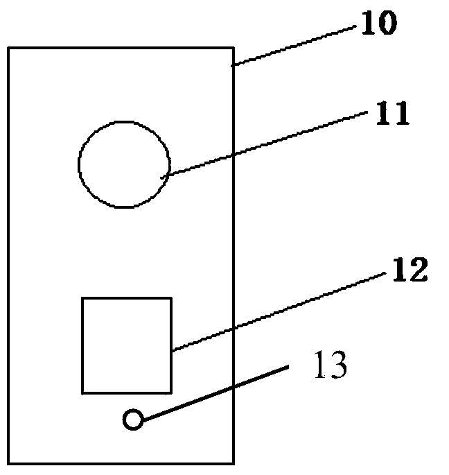
[0054] The central CPU 31 controls the electromagnet 12 through the relay 35 to carry out the unlocking operation, and after the optical cable transfer box is opened or closed, it sends a short message to the remote control terminal 6 through the short message communication module 32 to inform the lock body state. That is, when in use, the remote control terminal 6 (which may be a central industrial computer) can realize the control of multiple optical cable transfer boxes, and perform remote unlocking operations on multiple optical cable transfer boxes.

[0055] The controller 3 is provided with a lock body opening and closing state monitoring device 36, and the lock body opening and closing state ...


PUM


Abstract

The invention provides an optical-cable cross-connecting box door lock system. The optical-cable cross-connecting box door lock system comprises a lock body, a cabinet door touch switch, a door lock instruction transmitting unit, a controller, a short message communication module, a data server and a remote control terminal; the lock body comprises a mechanical lock body, a power supply switch and an electromagnet; the door lock instruction transmitting unit is installed on a mobile terminal of a user and used for transmitting an unlocking instruction to the controller. The optical-cable cross-connecting box door lock system is simple in structure and convenient to use, not only can an optical-cable cross-connecting box be opened by directly opening the mechanical lock body, but also the unlocking instruction can be directly transmitted by utilizing Bluetooth through the mobile terminal of the user, after the unlocking instruction is compared with pre-stored user information, the unlocking operation is actuated under the situation that the user information is correct, and the remote unlocking also can be carried out through the remote control terminal. Whether an optical-cable cross-connecting box door is illegally opened or not is monitored by utilizing the cabinet door touch switch, a monitoring early warning effect is achieved, and the safety of equipment can be guaranteed.

Description

technical field [0001] The invention relates to optical cable communication equipment, in particular to a door lock system for an optical cable transfer box. Background technique [0002] The distribution of communication pipelines is an indispensable link in urban public utilities. In order to beautify the city, a large number of communication optical cables or cable trunks are buried underground, but before they communicate with users, they must first extend out of the ground. The optical cable transfer boxes for some lines are set up on the street; and multiple optical cable transfer boxes also need to be set up during the long-distance transmission of optical fibers. Since these transfer boxes are set up outdoors, in addition to being waterproof and dustproof, they also need to be anti-theft to protect the safety and reliability of communication cables and ensure the privacy or commercial secrets of user communication information. [0003] However, the lockset of the pr...

Claims


Application Information

Patent Timeline
Patent Type & Authority Applications(China)
IPC IPC(8): G07C9/00
Inventor 李庆新范大磊张劲菁
Owner 北京立成通科技有限公司
Learn More