
Coordinate System Transformation Method for Detection of Vehicle Motion Acceleration

A coordinate system conversion and coordinate system technology, applied in the computer field, can solve the problems of affecting the vehicle attitude determination result, unable to recognize the axial acceleration, and unable to accurately evaluate the driver's driving behavior.

Active Publication Date: 2016-09-21
DALIAN ROILAND SCI & TECH CO LTD
View PDF5 Cites 0 Cited by
  • Summary
  • Abstract
  • Description
  • Claims
  • Application Information

AI Technical Summary

Problems solved by technology

[0003] In order to realize the detection of vehicle motion acceleration, plug-and-play vehicle-mounted equipment is generally used, which includes MEMS accelerometers and gyroscopes. Due to the limitations of the installation location and size, the installation of the vehicle-mounted equipment has greater randomness. installation problem
At present, the existing products on the market do not process the random installation position, directly collect the synthetic scalar information measured by the MEMS three-axis accelerometer, and cannot identify the acceleration of each axis in the vehicle's forward direction, lateral direction, and celestial three-dimensional coordinate system. For Driver's driving behavior cannot be accurately assessed
[0004] In view of the shortcomings of the existing technology in detecting the acceleration of vehicle motion, that is, regardless of the position and direction of the OBD interface, it can ensure that the measurement axis of the MEMS component is consistent with the direction of the vehicle, otherwise errors will occur, which will affect the vehicle attitude judgment results

Method used


Image

  • Coordinate System Transformation Method for Detection of Vehicle Motion Acceleration
  • Coordinate System Transformation Method for Detection of Vehicle Motion Acceleration
  • Coordinate System Transformation Method for Detection of Vehicle Motion Acceleration

Examples


Embodiment Construction

[0039] The specific implementation manners of the present invention will be further described in detail below in conjunction with the accompanying drawings and embodiments. The following examples are used to illustrate the present invention, but are not intended to limit the scope of the present invention.

[0040] A coordinate system transformation system for vehicle motion acceleration detection of the present invention includes: MEMS micro-electro-mechanical system (Micro-Electro-Mechanical System, MEMS) sensor, vehicle speedometer and global positioning system GPS. Among them, the MEMS sensor includes a MEMS three-axis accelerometer, a MEMS three-axis gyroscope and a MEMS three-axis magnetometer. The MEMS sensor represents the MEMS coordinate system (indicated by the letter M), and the vehicle speedometer represents the vehicle body coordinate system. (indicated by the letter B) and GPS is represented by a geographic coordinate system (indicated by the letter N).

[0041]...


PUM


Abstract

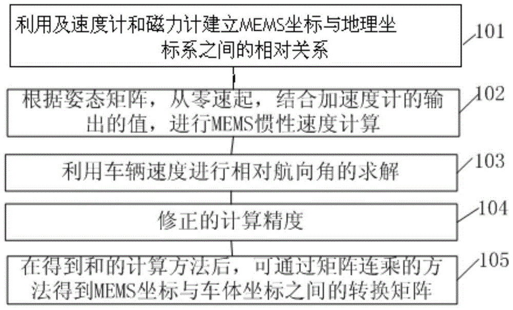
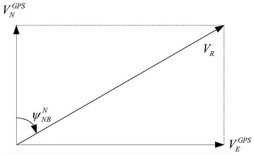
The invention relates to a coordinate system transformation method for detection of vehicle motion acceleration. The method includes the steps of establishing a correlative relationship between an MEMS (micro-electromechanical system) coordinate system and a geographic coordinate system through MEMS accelerometers and MEMS magnetometers; acquiring an attitude matrix according to outputs of the gyroscopes during navigation; according to the attitude matrix, acquiring a transformation matrix C<n><m> of the MEMS coordinate system and the geographic coordinate system; by the aid of the transformation matrix C<N><M>, transforming an acceleration output by the MEMS accelerometers into a geographic coordinate acceleration; according to a GPS (global positioning system) east velocity V<GPS><E> output by a GPS and a vehicle velocity V<R>, acquiring a relative course angle Psi<N><NB>; according to the related course angle, acquiring a transformation matrix C<N> from the geographic coordinate system to a vehicle body coordinate system; after a calculation method of the transformation matrix C<N> and the transformation matrix C<N><M> is acquired, acquiring a transformation matrix C<M> of the MEMS coordinate system and the vehicle body coordinate system by the Strassen algorithm; according to the transformation matrix C<M> of the MEMS coordinate system and the vehicle body coordinate system, transforming outputs of all of the MEMS gyroscopes and accelerometers to the vehicle body coordinate system.

Description

technical field [0001] The invention relates to the field of computers, in particular to a coordinate system conversion method for vehicle motion acceleration detection. Background technique [0002] At present, with the development of sensor technology and information processing technology, the application of vehicle acceleration detection in the field of automobile insurance is deepening, and the demand for the accuracy of acceleration vector measurement in vehicle motion is constantly increasing. [0003] In order to realize the detection of vehicle motion acceleration, plug-and-play vehicle-mounted equipment is generally used, which includes MEMS accelerometers and gyroscopes. Due to the limitations of the installation location and size, the installation of the vehicle-mounted equipment has greater randomness. Installation problem. At present, the existing products on the market do not process the random installation position, directly collect the synthetic scalar infor...

Claims


Application Information

Patent Timeline
Patent Type & Authority Patents(China)
IPC IPC(8): G01P15/18G01C21/16
Inventor 田雨农李刚周秀田
Owner DALIAN ROILAND SCI & TECH CO LTD
Learn More