Mechanism for bending pin width and enabling bending amount to be controlled conveniently

A control mechanism and bending technology, applied in the equipment field of network transformer manufacturing, to achieve the effect of accurate spacing deformation and simple structure

Inactive Publication Date: 2014-12-10
ZHONGJIANG KAIXUN ELECTRONICS
View PDF7 Cites 0 Cited by
  • Summary
  • Abstract
  • Description
  • Claims
  • Application Information

AI Technical Summary

Problems solved by technology

[0006] In order to solve the above problems, the mechanism for bending the pin width and the amount of bending that is easy to control provided by the present invention solves the problem through the following technical points: the mechanism for bending the pin width and the amount of bending is easy to control, including machine frame, a pressing bar arranged on the frame, a deformed press block fixed at the lower end of the press bar and a material platform located below the deformed press block, the press bar can move along its axial direction, and also includes a deformation control mechanism, the A pin tightening device is also fixed on the pressure rod;

Method used


Image

  • Mechanism for bending pin width and enabling bending amount to be controlled conveniently
  • Mechanism for bending pin width and enabling bending amount to be controlled conveniently
  • Mechanism for bending pin width and enabling bending amount to be controlled conveniently

Examples


Embodiment 1

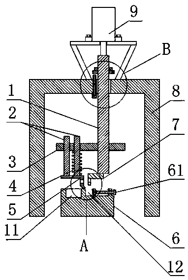
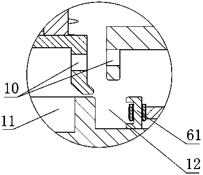
[0032] Such as Figure 1 to Figure 4As shown, the mechanism for bending the pin width and the amount of bending is easy to control, including a frame 8, a pressing bar 1 arranged on the frame 8, a deformation pressing block 7 fixed on the lower end of the pressing bar 1 and a deformation pressing block located at the bottom of the deformation pressing bar. The material table 6 below the block 7, the pressure rod 1 can move along its axial direction, and also includes a deformation control mechanism, and the pressure rod 1 is also fixed with a pin tightening device;

[0033] The pin tightening device comprises a spring seat 3, a spring 4 and a positioning pressing block 5, the spring seat 3 is fixed on the pressing bar 1, and the two ends of the spring 4 are fixedly connected with the spring seat 3 and the positioning pressing block 5 respectively, and the spring The axis of 4 is parallel to the axis of pressure rod 1, and the lower end position of positioning briquetting block...

Embodiment 2

[0042] The present embodiment is further limited on the basis of embodiment 1, as Figure 1 to Figure 4 As shown, in order to drive the pressing rod 1 conveniently, the upper end of the pressing rod 1 is also fixedly connected with a pressing rod driving part. According to the size of the workload, the set pressure rod driving part can be set in the structural form of artificial compressive stress drive or hydraulic pressure or air pressure drive.

[0043] In order to facilitate the working efficiency of the present invention, facilitate switching of working states and simplify the structure of the pressing rod driving part, the pressing rod driving part is an air cylinder 9 .

Embodiment 3

[0045] The present embodiment is further limited on the basis of embodiment 1, as Figure 1 to Figure 4 As shown, in order to prevent the positioning pressing block 5 from being skewed relative to the deformed pressing block 7 after the interaction force is generated with the pins, it also includes a guide rod 2, the axis of the guide rod 2 is in line with the The axes of the spring 4 are parallel, the lower end of the guide rod 2 is fixedly connected with the positioning pressure block 5 , and the spring seat 3 is also provided with a hole which is loosely matched with the guide rod 2 .

[0046] In order to enhance the ability to limit the movement direction of the positioning pressure block 5 and prevent the uneven deformation of the spring 4, there are more than one guide rod 2, and one of the guide rods 2 is located in the inner ring of the spring 4.


PUM


Abstract

The invention discloses a mechanism for bending the pin width and enabling the bending amount to be controlled conveniently. The mechanism comprises a rack, a pressing rod, a deformation pressing block and a material table, and further comprises a deformation control mechanism, and a pin fastening device is fixedly arranged on the pressing rod. The pin fastening device comprises a spring seat, a spring and a locating pressing block, the two ends of the spring are fixedly connected with the spring seat and the locating pressing block respectively, the axis of the spring is parallel to the axis of the pressing rod, and the lower end of the locating pressing block is lower than the lower end of the deformation pressing block. Containing holes are formed in the locating pressing block and the deformation pressing block respectively. A groove adjusting portion is arranged on the material table, and a groove is formed between the groove adjusting portion and the material table. The deformation control mechanism comprises an ejector rod bolt and a distance-fixed nut. The mechanism is simple in structure, the situation that the distance between pins is changed due to bending machining, and finally matching precision of the pins and pin holes is not high can be avoided, the mechanism is suitable for expanding or reducing pin bending of the width between the pins, and the deformation of the pins is controlled conveniently.

Description

technical field [0001] The invention relates to the field of equipment used in the manufacture of network transformers, in particular to a mechanism for bending the pin width and the bending amount is easy to control. Background technique [0002] Network transformers are widely used in high-performance digital switches; SDH / ATM transmission equipment; ISDN, ADSL, VDSL, POE power receiving equipment integrated business digital equipment; FILT optical fiber loop equipment; Ethernet switches and other equipment. [0003] The network transformer mainly includes a base, a cover, pins, and coils arranged between the pins. At the same time, the pins on the network transformer are generally arranged in two rows. In the prior art, the pins on the packaged network transformer are mostly needle-shaped. However, in practical applications, since the pin holes configured for the pins have different widths, it is often necessary to bend the pins to change the width between two rows of pin...

Claims


Application Information

Patent Timeline
Patent Type & Authority Applications(China)
IPC IPC(8): B21F1/00
Inventor 黄建国黄旭
Owner ZHONGJIANG KAIXUN ELECTRONICS
Why Eureka
Try Eureka