
an antenna

An antenna and antenna feeding technology, which is applied to antennas, resonant antennas, antenna components, etc., can solve the problems that the antenna bandwidth cannot be further widened and cannot meet the use requirements, and achieve the effect of expanding the working bandwidth

Active Publication Date: 2017-04-12
HUAWEI DEVICE CO LTD
View PDF11 Cites 0 Cited by
  • Summary
  • Abstract
  • Description
  • Claims
  • Application Information

AI Technical Summary

Problems solved by technology

[0005] In the existing technology, built-in antennas in the form of monopoles, IFAs, and PIFAs can improve the performance of the antenna, but cannot further widen the bandwidth of the antenna and cannot meet the actual use requirements

Method used


Image

  • an antenna
  • an antenna

Examples


Embodiment Construction

[0034] In order to make the object, technical solution and advantages of the present invention clearer, the implementation manner of the present invention will be further described in detail below in conjunction with the accompanying drawings.

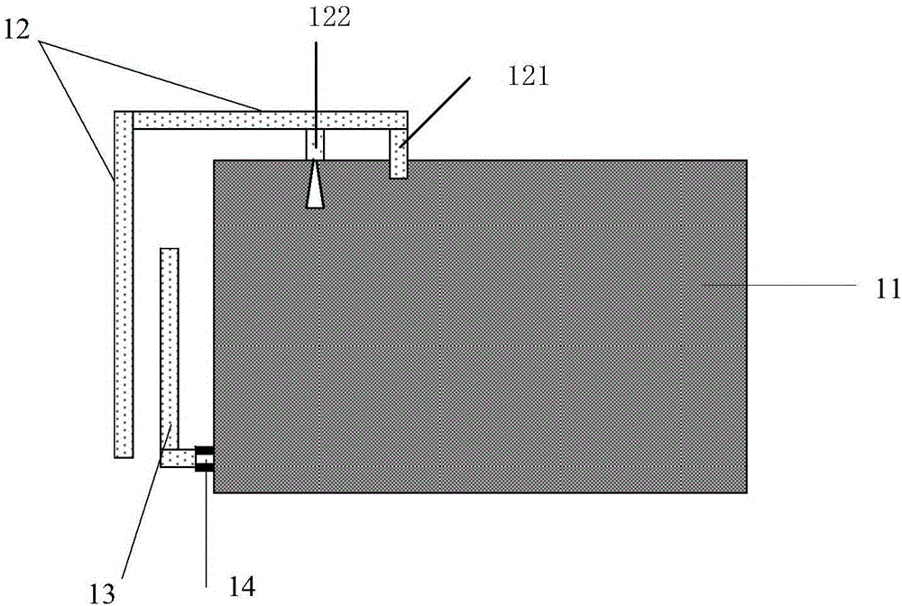
[0035] figure 1 is an antenna structure diagram provided in Embodiment 1 of the present invention, see figure 1 , the antenna includes at least:

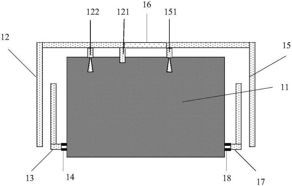
[0036] A printed circuit board 11, a first antenna feed structure 12, a first antenna load structure 13 and a first filter 14,

[0037] The first antenna feeding structure 12 has a grounding pin 121 and a feeding pin 122, the grounding pin 121 and the feeding pin 122 are respectively connected to the printed circuit board 11, the first antenna loading structure 13 The electric current forms a coupling structure with a part of the structure in the first antenna feeding structure 12;

[0038] The first antenna loading structure 13 is connected to the first filter 14, the first filter 14 is ...


PUM


Abstract

The invention discloses an antenna, which belongs to the technical field of communication. The antenna includes: a printed circuit board, a first antenna feeding structure, a first antenna loading structure and a first filter, the first antenna feeding structure has a ground pin and a feed pin, and the ground pin and the feed pin The pins are respectively connected to the printed circuit board, and the first antenna loading structure and a part of the first antenna feeding structure form a coupling structure; the first antenna loading structure is connected to the first filter , the first filter is connected to the printed circuit board, and the first filter is used to cut off low-frequency current. The filter cuts off the low-frequency current to realize the selective filtering of the antenna loading structure and expand the working bandwidth of the antenna.

Description

technical field [0001] The invention relates to the technical field of communications, in particular to an antenna. Background technique [0002] With the development of communication technology, terminal devices send and receive signals through built-in antennas to realize real-time communication. The development of LTE (Long Term Evolution, Long Term Evolution) has higher and higher requirements on the bandwidth of the antenna, completely covering all frequency bands of 2G, 3G, and 4G, which brings great challenges to antenna design. [0003] Built-in antennas in the form of monopoles, IFAs, and PIFAs are widely used in existing terminal equipment. These built-in antennas and PCBs together form a radiator for receiving and sending signals, which optimizes the performance of the antenna. [0004] In the process of realizing the present invention, the inventor finds that there are at least the following problems in the prior art: [0005] In the prior art, built-in antenna...

Claims


Application Information

Patent Timeline
Patent Type & Authority Patents(China)
IPC IPC(8): H01Q1/36H01Q1/38H01Q1/50H01Q5/00
CPCH01Q1/243H01Q9/42H01Q21/28H01Q5/314H01Q5/335H01Q5/378
Inventor 范毅孟博屠东兴孙树辉隆仲莹
Owner HUAWEI DEVICE CO LTD
Learn More