
Vertical pressing pulse condition driver

A driver and pulse technology, applied in the field of biomedical engineering, can solve the problems of inability to lift, press and find the pulse in traditional Chinese medicine, difficult miniaturization, complex structure, etc., and achieve the effect of convenient collection of pulse information and high-frequency pulse information collection

Active Publication Date: 2014-11-26
CHONGQING UNIV OF POSTS & TELECOMM
View PDF7 Cites 8 Cited by
  • Summary
  • Abstract
  • Description
  • Claims
  • Application Information

AI Technical Summary

Problems solved by technology

[0006] The existing related invention patents and researches have achieved pulse information collection to a certain extent, but there are still some deficiencies such as impreciseness and lack of layering in simulating finger pulse pulse "lifting, pressing, and searching", and the volume is too large and it is difficult to miniaturize, etc. Disadvantages, such as "a traditional Chinese medicine pulse detection system" (CN201310418535), the pulse signal acquisition device adopts a ring or ring structure, which is wrapped around the wrist, which cannot realize the lifting, pressing, and searching techniques of traditional Chinese medicine; another example is the multi-segment compound traditional Chinese medicine Although the pulse acquisition device (CN201310499382) is equipped with a "liftable arm", it can only roughly realize the three parts of "inch, guan and ruler" to cut the pulse and adjust the pressure. Adjustment can not realize the precise stratification of the pulse in modern pulse diagnosis, and lacks flexibility; also as the automatic feedback type regional pulse acquisition device (CN203388839U), a "pulse analog stick (5 mm × 5 mm in outer diameter)" is set, but The structure is complex and lacks application flexibility, and can only roughly realize pressure regulation, and cannot realize accurate stratification of the pulse in modern pulse diagnosis

Method used


Image

  • Vertical pressing pulse condition driver
  • Vertical pressing pulse condition driver
  • Vertical pressing pulse condition driver

Examples


Embodiment Construction

[0015] In order to make the purpose, technical solution and advantages of the present invention clearer, the pulse vertical pressing driver of the present invention will be further described in detail below in conjunction with the accompanying drawings.

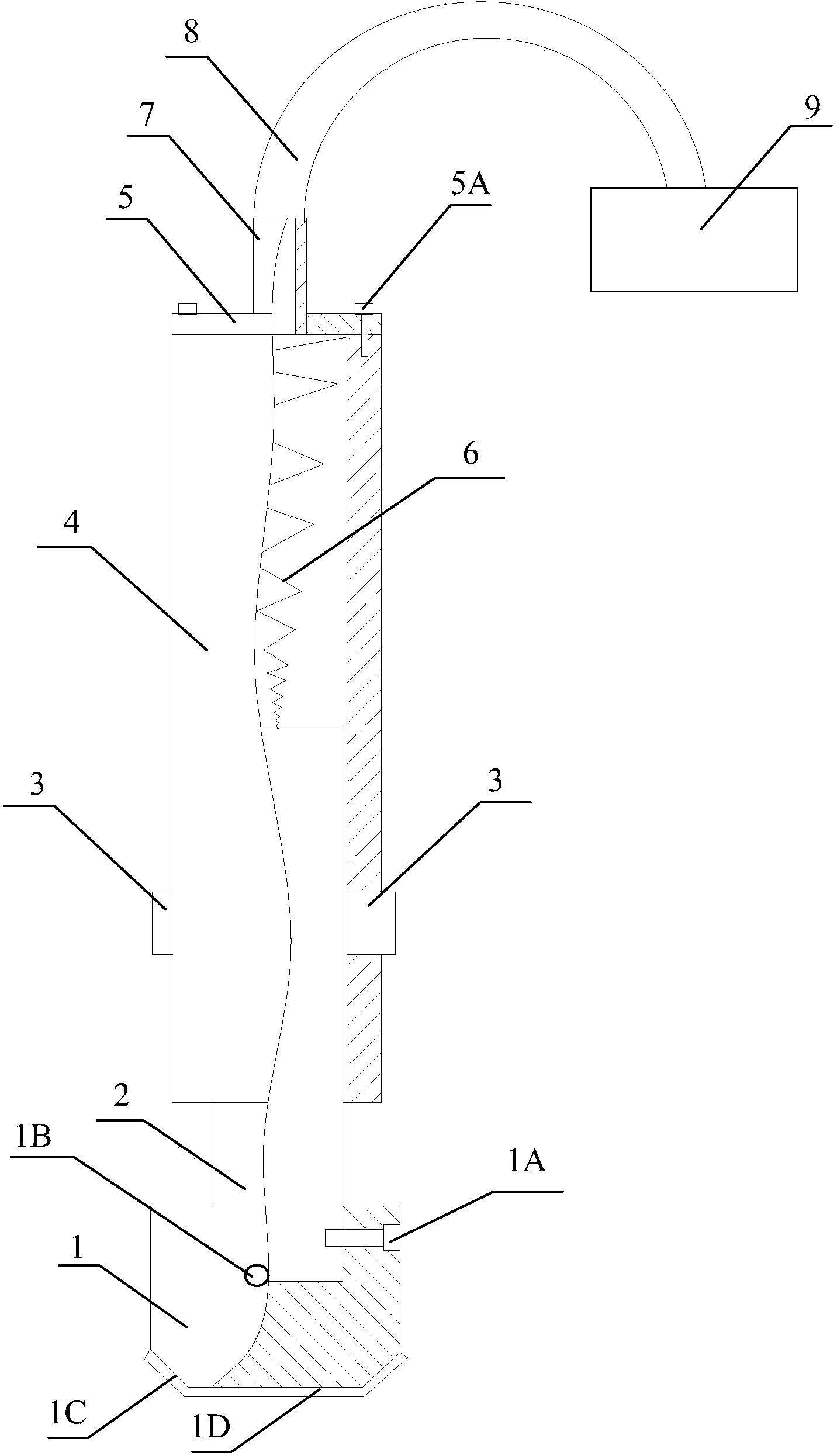
[0016] The pulse condition vertical pressing driver of the present invention, as figure 1 As shown, it includes an array pressing sensing probe 1, a piston 2, a piston locker 3, a driving tank 4, a tension spring 6, a packaging cover 5, a gas pipe 8 and a charging and discharging control device 9;

[0017] The lower end of the piston 2 is inserted into the groove on the upper surface of the array pressing sensing probe 1, the array pressing sensing probe 1 is fixedly connected to the lower end of the piston 2 through a screw 1A, and the piston 2 and the tension spring 6 are nested Set in the cavity of the driving tank 4, one end of the tension spring 6 is fixed on the upper end of the piston 2, and the other end of the tensio...


PUM


Abstract

The invention relates to the field of biomedical engineering, in particular to a vertical pressing pulse condition driver. The vertical pressing pulse condition driver comprises an array pressing sensing probe, a piston, piston locking devices, a driving tank, a tension spring, an encapsulation cover, an air pipe and an inflation and deflation control device. Pressure of the driving tank is raised through inflation of the inflation and deflation control device, the piston is pushed to move downwards, locking bolt bodies of locking bolts clamp sawteeth of blocking wings under the natural elastic force action of pressure springs, the piston is stabilized at a certain position where pressure is set, precise control over touching, pressing and searching force increasing is achieved and searching operations and pressing operations are carried out precisely and separately; the pressure of the driving tank is reduced through deflation of the inflation and deflation control device, acting force with which the piston is pulled upwards is generated through tension of the tension spring, electromagnetic driving blocks of the piston locking devices are controlled to generate magnetic attraction for attraction, pushing blocks are attracted to compress the springs, the sawteeth of the blocking wings are loosened from the locking bolt bodies of the locking blots, touching, pressing and searching force reduction is achieved and the searching operations and the pressing operations are achieved. Touching, pressing and searching pulse-taking of cun, guan and chi parts can be flexibly achieved.

Description

technical field [0001] The invention relates to the field of biomedical engineering, in particular to a pulse condition vertical pressing driver. Background technique [0002] Since the 1950s, a large number of scientific researchers have carried out a lot of research work on pulse theory, pulse diagnosis methods, clinical diagnosis and experiments, and made great progress. Up to now, the research on the objectification of pulse condition mainly focuses on the development of pulse condition instrument. [0003] The British Marey first developed the lever pulse sensor and recorded the radial artery pulse wave. In 1860, the lever and pressure drum first appeared to describe the pulse map. In 1895, the energy conversion method was used, and the lever optical pulse descriptor appeared. In the 1950s, Zhu Yan, a Chinese scholar, introduced the lever pulsograph for the first time in the study of TCM pulse diagnosis. Since the 1970s, researchers have developed a wide variety of tr...

Claims


Application Information

Patent Timeline
IPC IPC(8): A61B5/02
Inventor 曾垂省谢永芳胡波梁亦龙舒坤贤王允向浏欣罗志勇
Owner CHONGQING UNIV OF POSTS & TELECOMM
Learn More