
Multi-functional Planar Link Mechanism Demonstration Instrument and Its Realization Method

The technology of a planar linkage mechanism and its realization method, which is applied in the field of machinery, can solve the problems that restrict the development of university science classroom teaching, the insufficient variety of experimental teaching modes, and the incomplete popularization of innovative teaching aids, etc., and achieve beautiful appearance, saving purchase cost, and structure simple effect

Inactive Publication Date: 2017-05-03
BEIJING INSTITUTE OF GRAPHIC COMMUNICATION
View PDF7 Cites 0 Cited by
  • Summary
  • Abstract
  • Description
  • Claims
  • Application Information

AI Technical Summary

Problems solved by technology

In the development of today's education, although more and more classrooms use multimedia and other high-tech demonstrations in the classroom in an attempt to replace the traditional physical demonstration teaching mode, there are still some problems, such as the experimental teaching mode is not rich enough, the class In some experimental teaching, the teacher usually designs the purpose, content, and steps of the experiment in detail, and the students just do the experiment mechanically step by step. As a result, the students' experimental skills have not been improved, and the experimental classroom is pale and lacks exploratory nature innovative
Among them, the most important problems are the lack of experimental instruments in various colleges and universities, the incomplete popularization of innovative teaching aids, etc., which restrict the development of university science classroom teaching.

Method used


Image

  • Multi-functional Planar Link Mechanism Demonstration Instrument and Its Realization Method
  • Multi-functional Planar Link Mechanism Demonstration Instrument and Its Realization Method
  • Multi-functional Planar Link Mechanism Demonstration Instrument and Its Realization Method

Examples


Embodiment Construction

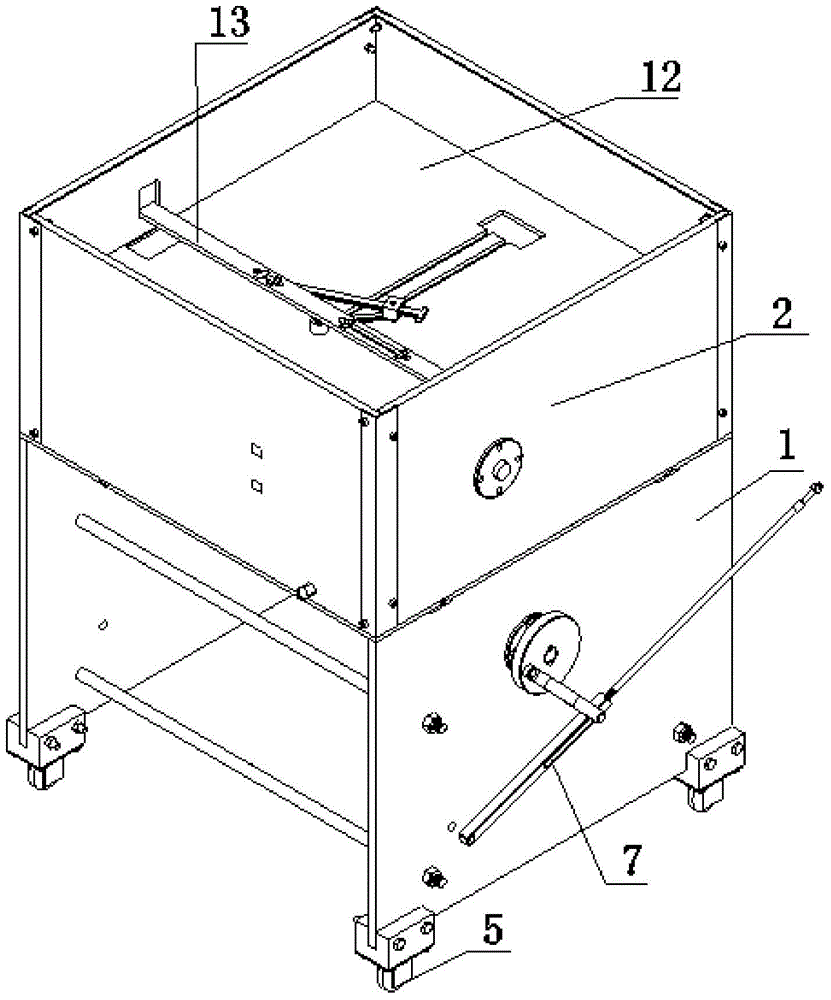
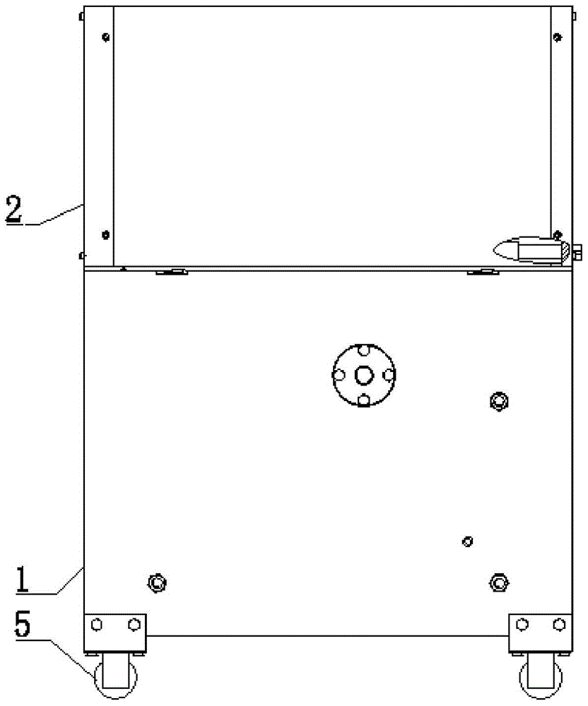
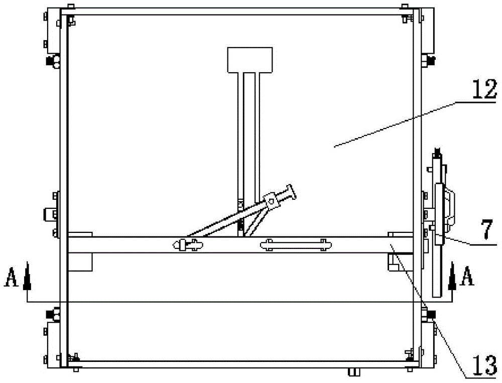
[0049] Such as Figure 1-Figure 4 As shown, it is a schematic structural view of the multifunctional planar linkage demonstrator of the present invention, as can be seen from the figure, the multifunctional planar mechanism demonstrator of the present invention includes: a plurality of parts for forming various planar linkages; A demonstration platform provided with a plurality of preset holes for defining the installation positions of a plurality of parts; a power transmission mechanism whose output shaft is connected with a crank in the plurality of parts; wherein, the corresponding parts are selected according to the needs of the required demonstration planar linkage mechanism , install the corresponding parts in the corresponding preset holes, and connect the corresponding parts correspondingly; wherein, the crank in the corresponding parts is connected with the output shaft, so that the corresponding parts can be demonstrated under the drive of the power transmission mecha...


PUM


Abstract

The invention discloses an implementation method of a multifunctional planar mechanism demonstration instrument. The implementation method comprises the following steps that a plurality of parts used for forming various planar link mechanisms are arranged; a plurality of preset holes used for limiting the installation positions of the parts are formed in a demonstration platform; corresponding parts required by one planar link mechanism needing to be demonstrated are selected, the corresponding parts are installed in corresponding preset holes, and the corresponding parts are correspondingly connected; a crank in the corresponding parts is connected with an output shaft of a power transmission mechanism so that the planar link mechanism can be demonstrated through the corresponding parts through driving of the power transmission mechanism. The invention further provides the demonstration instrument which is simple in structure, various planar link mechanisms can be assembled according to demonstration requirements, a demonstrator can carry out assembly and operation by himself / herself, assembly is fast to carry out, and the kinematic principle and the principle of dynamics of various planar link mechanisms can be clearly showed.

Description

technical field [0001] The invention relates to the field of machinery, in particular to a multifunctional planar link mechanism demonstrator for teaching demonstration and a realization method thereof. Background technique [0002] In teaching, planar mechanism is a type of mechanism that is mainly described in commonly used mechanisms. The characteristics of this type of mechanism include many sub-structures, many practical application examples, many concepts, many pictures, the content is closely related to practice, and the abstraction is difficult to understand. [0003] Today's education reform is based on comprehensively promoting quality education as the core, and is based on the implementation of innovative education and practical education. In the development of today's education, although more and more classrooms use multimedia and other high-tech demonstrations in the classroom in an attempt to replace the traditional physical demonstration teaching mode, there a...

Claims


Application Information

Patent Timeline
Patent Type & Authority Patents(China)
IPC IPC(8): G09B25/02
Inventor 赵世英吴凡吴夏野王艺龙李思遥金兴彪
Owner BEIJING INSTITUTE OF GRAPHIC COMMUNICATION
Learn More