
Repeatedly opened and closed anti-leakage valve with cylindrical panel valve sealing structure

A valve sealing and panel technology, which is applied in the field of safety isolation devices, can solve problems affecting the opening of plate valves, and achieve long-term safe and reliable use

Active Publication Date: 2014-11-19
DRIPRO
View PDF5 Cites 7 Cited by
  • Summary
  • Abstract
  • Description
  • Claims
  • Application Information

AI Technical Summary

Problems solved by technology

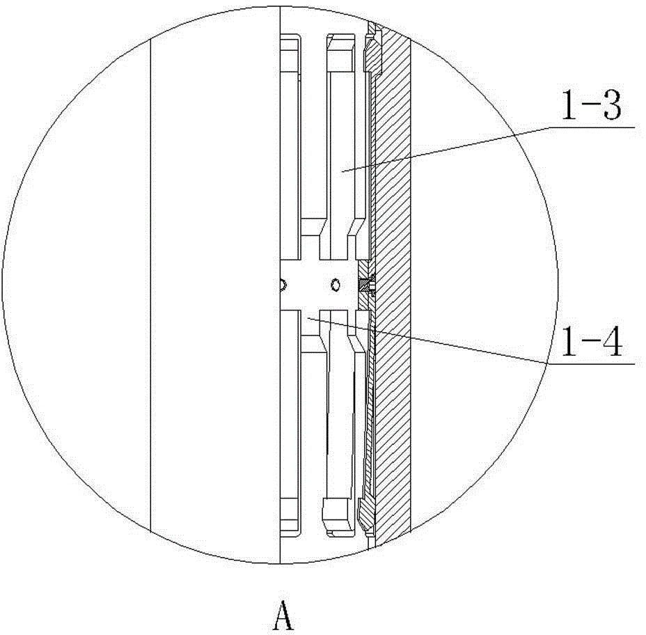
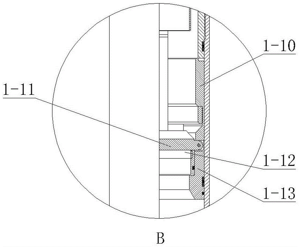
[0004] Aiming at the problems existing in the prior art, the object of the present invention is to provide a multi-time switch leakage prevention valve provided with a plate valve sealing structure, wherein the valve plate and the valve seat are sealed with a cylindrical surface, and the valve plate is upward relative to the valve seat. Opening can solve the problem of sand or falling objects falling on the valve body and affect the opening of the plate valve. At the same time, it can ensure that the valve body has a large internal diameter, and it can also ensure the reliability of the seal in a long-term high-pressure environment.

Method used


Image

  • Repeatedly opened and closed anti-leakage valve with cylindrical panel valve sealing structure
  • Repeatedly opened and closed anti-leakage valve with cylindrical panel valve sealing structure
  • Repeatedly opened and closed anti-leakage valve with cylindrical panel valve sealing structure

Examples


Embodiment Construction

[0044] In order to further explain the technical means and functions adopted by the present invention to achieve the predetermined technical purpose, the structure and working process of the present invention are described in detail below in conjunction with the accompanying drawings and preferred embodiments.

[0045] The anti-leakage valve described in the present invention needs to be opened with a special switch tool. The switch tool can be a switch tool in the prior art, such as the switch tool described in the Chinese utility model patent (CN201507274U). The invention also provides a A switch tool with more reliable performance, the detailed structure is described in the second part below.

[0046] 1. Anti-leakage valve

[0047] Such as figure 1 , Figure 4 , Figure 9 Shown is a schematic diagram of the anti-leakage valve 1 used in the present invention. The anti-leakage valve 1 includes a valve body, and the valve body is composed of a positioning joint 1-1, a loc...


PUM


Abstract

The invention discloses a repeatedly opened and closed anti-leakage valve with a cylindrical panel valve sealing structure. The anti-leakage valve comprises a valve body formed by combining a positioning connector, a locking cylinder and a lower connector, and a tubular mandrel a capable of moving in a reciprocating mode is arranged in the valve body and driven by an opening and closing tool to move in the reciprocating mode; a valve plate and a valve base which are matched are arranged at the position, close to the lower end, in the valve body, the valve plate is installed on a supporting base and arranged close to one side of the mandrel a, the supporting base is fixed to the inner wall of the valve body, and the valve base can move in a reciprocating mode in the axis direction of the valve body. When the anti-leakage valve is opened, the mandrel a moves downwards, the valve base is pushed to move downwards through a transmission mechanism, and when continuing to move downwards to make contact with the valve plate, the mandrel a pushes the valve plate to rotate in the side direction so that the anti-leakage valve can be opened; when the anti-leakage valve is closed, the mandrel a moves upwards, the valve plate is automatically reset under the action of a reset spring, and the mandrel a continues to move upwards and drives the valve base through the transmission mechanism to move upwards to press the valve plate in an abutting-against mode so that the anti-leakage valve is closed. The contact faces of the valve plate and the valve base are cylindrical surfaces.

Description

technical field [0001] The invention relates to a safety isolation device used in oil drilling and oil field production, and belongs to the technical field of oil well equipment. Background technique [0002] At present, some of the anti-leakage valves used in the downhole environment of oil exploitation use ball valve sealing devices. For example, a Chinese utility model patent (CN201507274U) describes an anti-leakage valve that adopts a ball valve sealing structure. The core inside the valve body The shaft can drive the ball valve to open or close. There is an elastic tab (also called: elastic finger) above the mandrel. When the switch tool extends into the valve body, it cooperates with the protrusion at the end of the elastic tab to drive the mandrel to move up and down to realize the anti-leakage valve. on and off. [0003] However, the internal diameter of the ball valve sealing device is small, so more and more plate valve sealing devices are used. The valve plate i...

Claims


Application Information

Patent Timeline
IPC IPC(8): F16K1/20F16K1/32E21B34/06E21B33/10
CPCE21B33/10E21B34/06F16K1/2007F16K1/2014
Inventor 任峰德郭武兵唐文波
Owner DRIPRO
Learn More