An Idle Speed ​​Control Valve with Switchable Magnetic Field Direction

A technology of idle speed control valve and magnetic field direction, applied in engine control, machine/engine, mechanical equipment, etc., can solve problems such as shaft movement delay

Active Publication Date: 2017-01-25
江苏宝绣园文旅发展有限公司
View PDF4 Cites 0 Cited by
  • Summary
  • Abstract
  • Description
  • Claims
  • Application Information

AI Technical Summary

Problems solved by technology

[0004] Based on the technical problems existing in the background technology, the present invention proposes an idle speed control valve with switchable magnetic field direction, which solves the problem of shaft motion delay

Method used


Image

  • An Idle Speed ​​Control Valve with Switchable Magnetic Field Direction
  • An Idle Speed ​​Control Valve with Switchable Magnetic Field Direction

Examples


Embodiment Construction

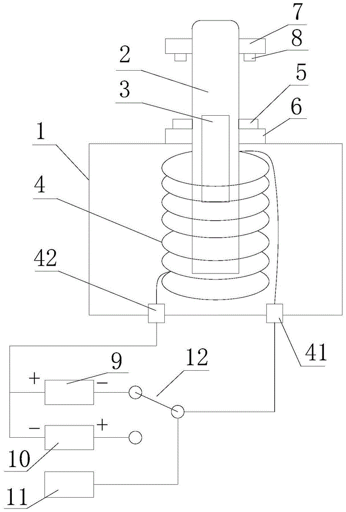
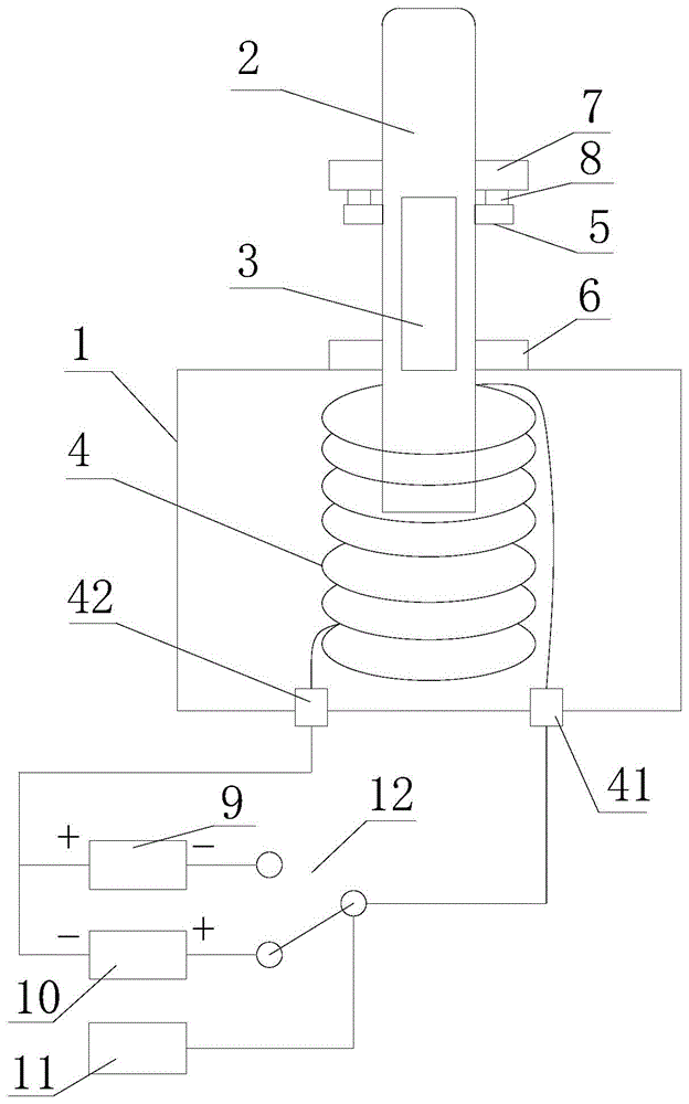
[0018] refer to figure 1 , figure 2 , an idle speed control valve with a switchable magnetic field direction proposed by the present invention, including a housing 1, a shaft body 2, a permanent magnet 3, an electromagnetic coil 4, a locking member 5, a first buffer pad 6, a limiting member 7, a second A cushion pad 8 , a first power source 9 , a second power source 10 , an ECU (Electronic Control Unit, electronic control unit) module 11 and a switch 12 .

[0019] The first end of the shaft body 2 is inserted into the casing 1 , the permanent magnet 3 is installed inside the shaft body 2 , and the magnetic pole direction of the permanent magnet 3 is parallel to the length direction of the shaft body 2 .

[0020] The first buffer pads 6 are installed on the housing 1 and are circumferentially distributed outside the shaft body 2 . The limiting member 7 is installed near the second end of the shaft body 2 and distributed circumferentially outside the shaft body 2 , and the se...


PUM


Abstract

The invention provides an idle air control valve with the switchable magnetic field directions. The idle air control valve comprises an outer shell, a shaft, a permanent magnet, an electromagnetic coil, a position buckling piece, a first buffering gasket, a limiting piece, a second buffering gasket, a first power source, a second power source, an ECU module and a change-over switch. The first end of the shaft is inserted into the outer shell, the permanent magnet is installed inside the shaft, the magnetic pole direction of the permanent magnet is parallel to the length direction of the shaft, the first buffering gasket is installed on the outer shell and circumferentially distributed on the outer side of the shaft, the limiting piece is installed at the position close to the second end of the shaft and circumferentially distributed on the outer side of the shaft, the second buffering gasket is installed on the side, close to the first buffering gasket, of the limiting piece, the position buckling piece is arranged on the shaft and located between the first buffering gasket and the second buffering gasket, and the electromagnetic coil is installed inside the outer shell and arranged on the periphery of the shaft in a sleeved mode. By means of the idle air control valve with the switchable magnetic field directions, the movement delay problem of the shaft is solved.

Description

technical field [0001] The invention relates to the technical field of idle speed control valves, in particular to an idle speed control valve with a switchable magnetic field direction. Background technique [0002] The idle speed control valve is powered by the ignition switch, as long as the ignition switch is turned to the ON position, the idle speed control valve is powered on, and the engine computer controls its circuit to ground. This valve is used to adjust the idle speed when the engine's operating parameters deviate from normal values. Idle speed is adjusted by controlling the amount of air bypassing the throttle body. After the engine is started, the idle speed control valve is opened for a period of time to increase the intake air, which increases the idle speed of the engine by approx. When the engine coolant temperature is low, the idle speed control valve opens to obtain a proper fast idle speed. The engine computer controls the position of the plunger of ...

Claims


Application Information

Patent Timeline
Patent Type & Authority Patents(China)
IPC IPC(8): F02D9/08
Inventor 陈清海陈青山
Owner 江苏宝绣园文旅发展有限公司
Why Eureka
Try Eureka