A built-in tire burst emergency device with multiple oil cylinders

An emergency device and oil cylinder technology, applied in tire parts, transportation and packaging, vehicle parts, etc., can solve problems such as power supply for difficult vehicles, and achieve the effect of smooth and comfortable driving of vehicles

Active Publication Date: 2017-01-18
启东捷顺科技创业园有限公司
View PDF8 Cites 0 Cited by
  • Summary
  • Abstract
  • Description
  • Claims
  • Application Information

AI Technical Summary

Problems solved by technology

Embodying the third design idea is the anti-explosion rim inside the tire announced by the Chinese utility model with the announcement number 203713430, but the anti-explosion rim inside the tire has the defect that it is difficult to provide power for the vehicle

Method used


Image

  • A built-in tire burst emergency device with multiple oil cylinders
  • A built-in tire burst emergency device with multiple oil cylinders
  • A built-in tire burst emergency device with multiple oil cylinders

Examples


Embodiment 1

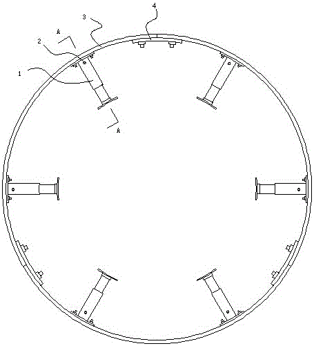
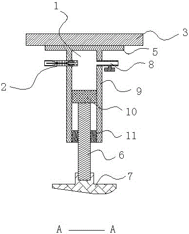
[0023] Such as figure 1 , figure 2 , image 3 As shown, this embodiment includes a cylinder formed by connecting three main body arcs 3 , and the adjacent main body arcs 3 are detachably fixedly connected by connecting structures. Both ends of the main body arc 3 are provided with connecting screws (not marked), the connecting screw (not marked) is located on the side of the main body arc 3 facing the center of the circle, and the connecting screw (not marked) is integrally cast with the main body arc 3; the connection The structure includes a connecting screw (not marked), a connecting arc 4, and a connecting nut (not marked). The connecting arc 4 is provided with a through hole (not shown) for the connecting screw (not marked) to pass through; the adjacent main body circle Arc 3 is fixedly connected by connecting screw rod (not marked), connecting arc 4 and connecting nut (not marked).

[0024] Two oil cylinders 1 are arranged on each main body arc 3, and oil cylinder 1 ...

Embodiment 2

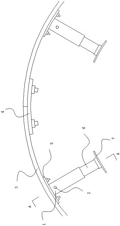
[0027] Such as Figure 4 , Figure 5 , Figure 6 As shown, this embodiment includes a cylinder formed by connecting three main body arcs 3 , and the adjacent main body arcs 3 are detachably fixedly connected by connecting structures. The main body arc 3 includes a support section 3-1 in the middle and connecting sections 3-2 at both ends; the radial thickness of the main body arc 3 is at the junction of the connecting section 3-2 and the supporting section 3-1. Step, the radial thickness of the connecting section 3-2 is thinner than the radial thickness of the supporting section 3-1; the connecting section 3-2 is provided with a connecting screw (not marked) on the side facing the center of the circle, and the connecting screw (not marked) is connected with the connecting Section 3-2 is integrally cast. The connection structure includes a connecting screw (not marked), a connecting arc 4, and a connecting nut (not marked), and the connecting arc 4 is provided with a through...


PUM


Abstract

The invention provides a built-in tire burst emergency device used for a vacuum tire and equipped with multiple oil cylinders. The emergency device comprises a cylinder formed by connection of two or more than two main body arcs; every two adjacent main body arcs are detachably and fixedly connected through a connection structure; each main body arc is at least provided with one oil cylinder; the oil cylinder comprises a cylinder barrel, a piston, a piston rod and a guide sleeve, wherein the rear end of the cylinder barrel is an enclosed end and is fixedly mounted on the side of the main body arc facing the center of circle, the cylinder barrel is further provided with a non-return valve and a fuel drain valve, the piston is mounted in the cylinder barrel, the guide sleeve is fixedly arranged at the front end of the cylinder barrel, the rear end of the piston passes through the guide sleeve, then extends into the cylinder barrel and is eventually connected with the piston, and the front end of the piston is fixedly provided with a friction pad. When a vehicle equipped with the tire burst emergency device undergoes tire burst, the inclination degree of the center of gravity of the vehicle body is small, a burst tire can be used as a power wheel of the vehicle, and installation of the emergency device can be carried out without reconstruction of wheel rims of the wheels of the vehicle.

Description

technical field [0001] The invention relates to the field of tire blowout emergency devices for motor vehicles, in particular to a built-in tire blowout emergency device for vacuum tires. Background technique [0002] When a car equipped with vacuum tires blows out during driving, the outer tire will sag toward the groove of the rim, or even fall off, so that the rim of the rim replaces the outer tire to support the ground. On the one hand, the center of gravity of the vehicle body tilts toward the side of the punctured wheel due to the dent or even falling off of the outer tire, which is prone to rollover; direction control. Therefore, for the vehicle in the running process, especially the vehicle in the high-speed running, the tire blowout can easily lead to traffic accidents, and even lead to the tragedy of car crash. [0003] In the prior art, the design thinking of the vacuum tire blowout emergency device can be summarized into three types. The first is to block the ...

Claims


Application Information

Patent Timeline
Patent Type & Authority Patents(China)
IPC IPC(8): B60C17/04
Inventor 蒋凤英
Owner 启东捷顺科技创业园有限公司
Why Eureka
Try Eureka