Breaking device for isolating switch and isolating switch using the same

A technology of isolating switch and circuit breaker, which is applied in the field of folding isolating switch, which can solve the problems of being unable to use the ultra-high voltage isolating switch busbar switch, not being able to meet the requirements of the ultra-high voltage isolating switch, and contact burnout, so as to avoid long-term live current Effect

Active Publication Date: 2016-06-01
STATE GRID CORP OF CHINA +2
View PDF3 Cites 0 Cited by
  • Summary
  • Abstract
  • Description
  • Claims
  • Application Information

AI Technical Summary

Problems solved by technology

The foldable isolating switch includes the moving and static contacts of the isolating switch arranged at the front and rear and the foldable conductive rod arranged between the moving and static contacts of the isolating switch. The contact connection end of the contact rod can realize the opening and closing between the dynamic and static contacts of the disconnector through horizontal folding action. With the development of series compensation technology, after the power system adopts series compensation device, the isolation switch The current that needs to be broken has reached 6300A, and its recovery voltage has reached 7000V. At this time, it is impossible to use the air break to break such a large current. Because the disconnector cannot eliminate the arc, the contact burns seriously and cannot be used for ultra-high voltage isolation. Switching between switch busbars cannot meet the requirements of extra-high voltage isolating switches in special occasions (such as bypass isolating switches)

Method used


Image

  • Breaking device for isolating switch and isolating switch using the same
  • Breaking device for isolating switch and isolating switch using the same
  • Breaking device for isolating switch and isolating switch using the same

Examples


Embodiment Construction

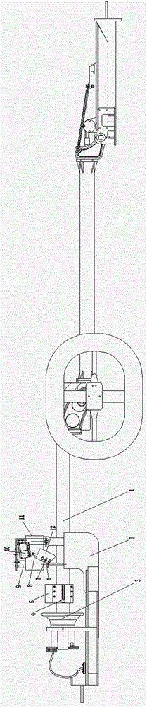
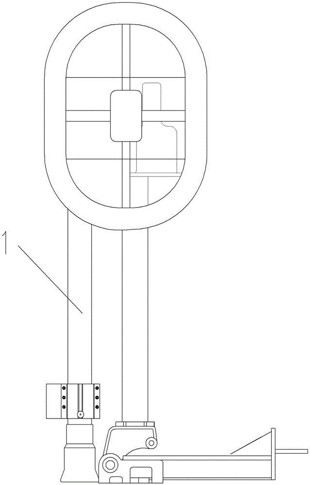
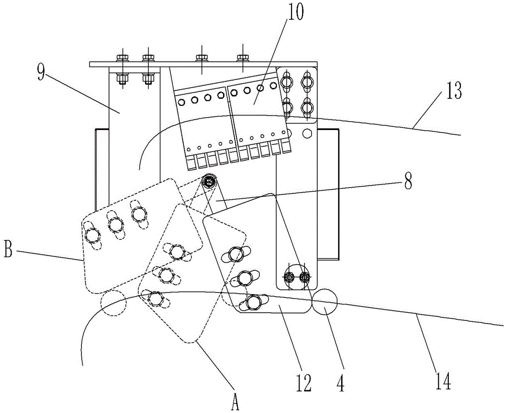
[0021] Examples of isolating switches are Figure 1~6 Shown: including the movable contact of the isolating switch, the static contact 3 of the isolating switch, and the foldable conductive rod 1 used to realize the opening and closing of the movable and static contacts of the isolating switch. Line 14 indicates that the conductive rod is in operation. The motion trajectory driven by the mechanism, the conductive rod and the operating mechanism driving the conductive rod all belong to the prior art, and will not be described in detail here. The isolating switch also includes a breaking device. The breaking device includes a moving side breaking device arranged on the conductive rod and a static side breaking device arranged next to the static contact of the isolating switch. The frame body 11 arranged on the static contact of the isolation switch is provided with a vacuum circuit breaker 9. The vacuum circuit breaker includes a vacuum type arc extinguishing chamber with moving...


PUM


Abstract

The invention relates to a breaking device for a disconnecting switch and the disconnecting switch using the same. The breaking device comprises a movable breaking device and a static breaking device, wherein the static breaking device comprises a circuit breaker, the circuit breaker comprises an arc extinguishing chamber and an operation handle, the operation handle has a switching position and a closing position which are used for driving a movable contact and a static contact of the arc extinguishing chamber into a switching state and a closing state during rotation of the operation handle around a rotation axis thereof, the movable breaking device comprises a shift rod fixedly arranged on a corresponding conductive rod, and a shift structure is arranged on the shift rod, and used for shifting the operation handle to be rotated into the closing position from the switching position before the movable contact and the static contact of the disconnecting switch are closed during closing of the conductive rod and shifting the operation handle to be rotated into the switching position from the closing position after the movable contact and the static contact of the disconnecting switch are switched during switching of the conductive rod. By the disconnecting device provided by the invention, the disconnecting switch has the ability of disconnecting large current, and the arc distinguishing chamber can be prevented from being energized for a long time due to serial connection of an auxiliary contact with the arc distinguishing device.

Description

technical field [0001] The invention relates to high-voltage electrical equipment, in particular to a breaking device for an isolating switch and a foldable isolating switch using the breaking device. Background technique [0002] As an outdoor high-voltage isolating switch with an air break, its main function is to provide electrical isolation for high-voltage electrical equipment under no-load conditions, so the isolating switch does not have the ability to break the rated current. This isolation can be used for daily operations or for high-voltage equipment. maintain. The foldable isolating switch includes the moving and static contacts of the isolating switch arranged at the front and rear and the foldable conductive rod arranged between the moving and static contacts of the isolating switch. The contact connection end of the contact, the conductive rod can realize the opening and closing between the dynamic and static contacts of the disconnector through horizontal fol...

Claims


Application Information

Patent Timeline
Patent Type & Authority Patents(China)
IPC IPC(8): H01H33/02H01H33/12H01H33/46
Inventor 胡延涛王占杰孙玉洲王巧红马永旭赵维全夏立国张任尹天朔
Owner STATE GRID CORP OF CHINA
Why Eureka
Try Eureka