A Method of Finding Satellites with an Antenna in Motion

A mobile communication and antenna technology, applied to antennas, electrical components, etc., can solve problems such as low precision, decreased tracking performance, and decreased success rate of finding stars, so as to achieve improved reliability and accuracy, good tracking accuracy, and high reliability Effect

Active Publication Date: 2016-08-24
北京星网卫通科技开发有限公司
View PDF3 Cites 0 Cited by
  • Summary
  • Abstract
  • Description
  • Claims
  • Application Information

AI Technical Summary

Problems solved by technology

This solution has high requirements on the inertial navigation system. In order to ensure that the antenna can lock the largest satellite signal, the autonomous north-seeking accuracy of the inertial navigation system must reach more than 0.1°, and the cost of such a high-precision inertial navigation system has far exceeded The cost of the mobile communication antenna itself is unaffordable for most development units and users
In order to effectively reduce the cost, a low-precision and low-cost inertial navigation system must be selected, and the low-precision inertial navigation system cannot autonomously find the north to output the correct heading, so the antenna cannot obtain accurate command angles to the star
In order to solve the problem of antenna initialization in motion based on low-precision inertial navigation, most research and development units currently use antenna azimuth axis 0°-360° scanning and satellite beacon signal peak recognition technology to realize antenna star-seeking, but the antenna star-seeking process However, there is no function of isolating the motion of the carrier. When the carrier is in motion, the success rate of star-seeking will be greatly reduced. In addition, the existing star-seeking algorithms rely solely on AGC (Adaptive Gain Control, automatic gain control) level to find Satellites do not have the means of assigning inertial navigation values ​​by coarse-scan star-finding and fine-scanning satellite-finding to fine-tune the inertial navigation direction. This method, after the antenna is turned into the tracking state, will not eliminate the error of the inertial navigation system, the tracking performance will be degraded. declined
In addition, the currently disclosed satellite-finding methods for mobile communication antennas are mainly aimed at the initial satellite-finding method after the system is powered on, and there is no systematic description and discussion of the satellite-finding strategies for all situations encountered during the use of mobile communication antennas.

Method used


Image

  • A Method of Finding Satellites with an Antenna in Motion
  • A Method of Finding Satellites with an Antenna in Motion
  • A Method of Finding Satellites with an Antenna in Motion

Examples


Embodiment Construction

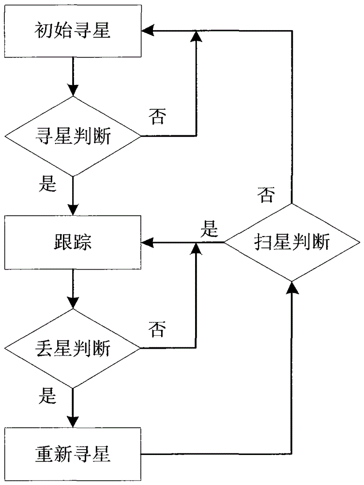
[0032] 1. A satellite-seeking method for antennas in motion, such as figure 1 shown, including the following steps:

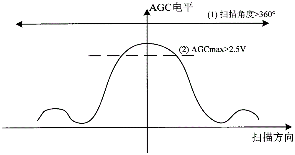
[0033] (1) Before the antenna is initially powered on and enters the tracking state, the antenna conducts initial star-seeking, and determines whether the satellite signal has been found through the star-finding judgment; after the antenna is turned on and homing is completed, it will automatically search for the satellite according to the information of the satellite to be tracked, Described initial star search comprises the following steps (as figure 2 shown):

[0034] 1) Set the beacon frequency of the antenna to the single carrier frequency of the satellite to be tracked;

[0035] 2) The azimuth angle of the antenna is rotated clockwise at a speed of 15° / s for rough scanning, and the pitch and polarization angles of the antenna are respectively isolated from the horizontal attitude of the carrier, so that the antenna can always maintain the spatial leve...


PUM


Abstract

A method for finding satellites with an antenna in motion, comprising the following steps: before tracking, the antenna carries out initial star-seeking, and confirms whether a satellite signal has been found through a star-finding judgment criterion; during tracking, monitors the AGC level signal at all times, and performs Judgment of star loss; after tracking and losing lock, start to search for stars again and perform star scan judgment; if a satellite signal is found, it will enter the tracking state; .

Description

technical field [0001] The invention relates to a star-seeking method for a mobile communication antenna, which is used in the field of stable tracking control of the mobile communication antenna. Background technique [0002] The mobile communication antenna can ensure that the antenna surface is always aligned with the geosynchronous satellite on the mobile carrier, and realize high-bandwidth real-time image and data transmission. It has a very wide application prospect in national defense, frontier defense, anti-terrorism, emergency relief, government and other departments. [0003] The mobile communication antenna is composed of two parts: the antenna feed system and the servo control system. Antenna feeder system includes antenna surface, duplexer, filter, down converter, up converter, waveguide and other components, which constitute the basic elements of a satellite communication system; the servo control system needs to drive the antenna surface to complete functions ...

Claims


Application Information

Patent Timeline
Patent Type & Authority Patents(China)
IPC IPC(8): H01Q3/08
Inventor 徐烨烽
Owner 北京星网卫通科技开发有限公司
Why Eureka
Try Eureka