Injection molding machine
A technology of injection molding machine and locking mechanism, applied in the field of injection molding machine, to achieve the effect of improving balance and improving clamping force
- Summary
- Abstract
- Description
- Claims
- Application Information
AI Technical Summary
Problems solved by technology
Method used
Image

Examples
no. 1 Embodiment approach
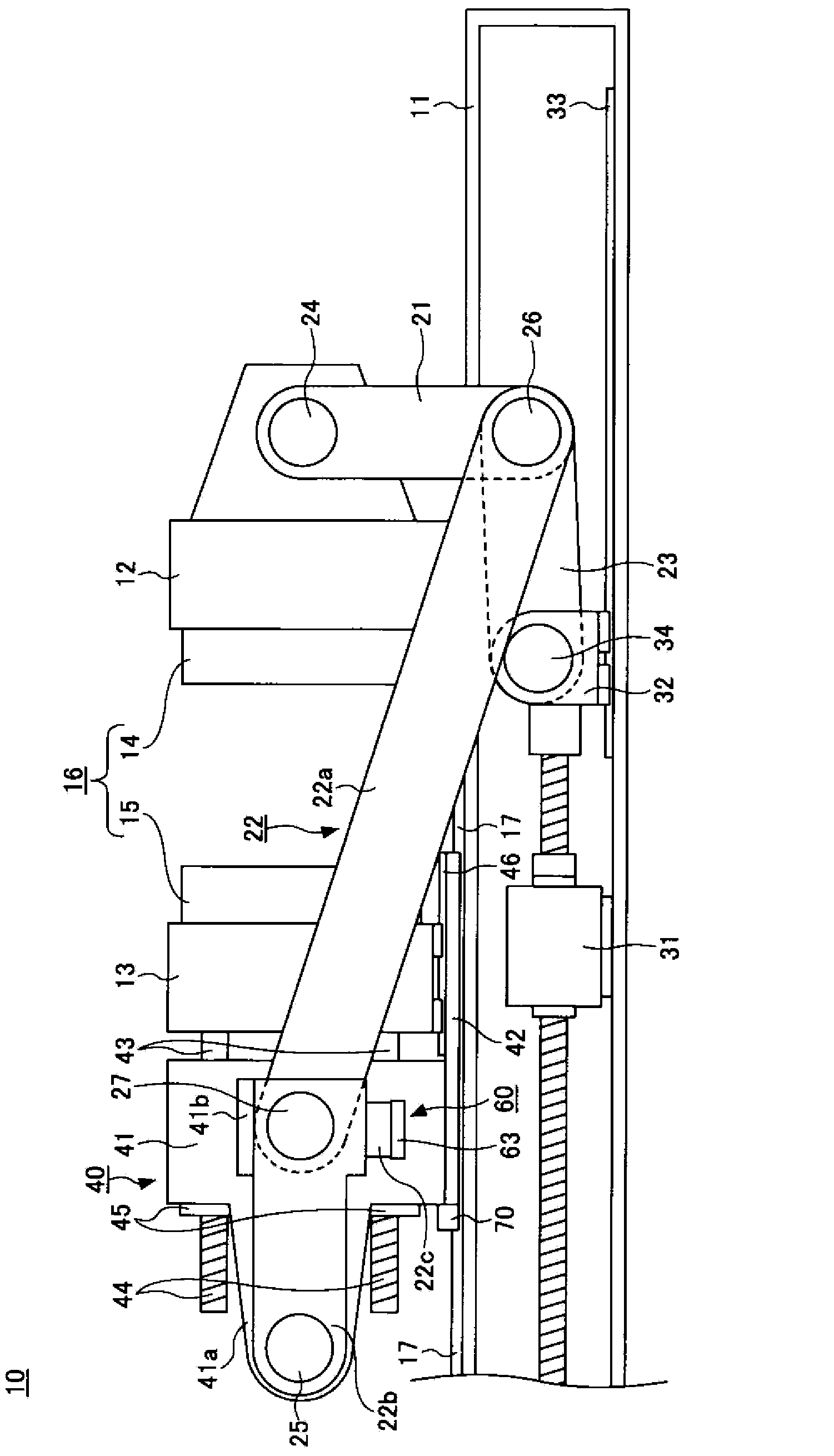
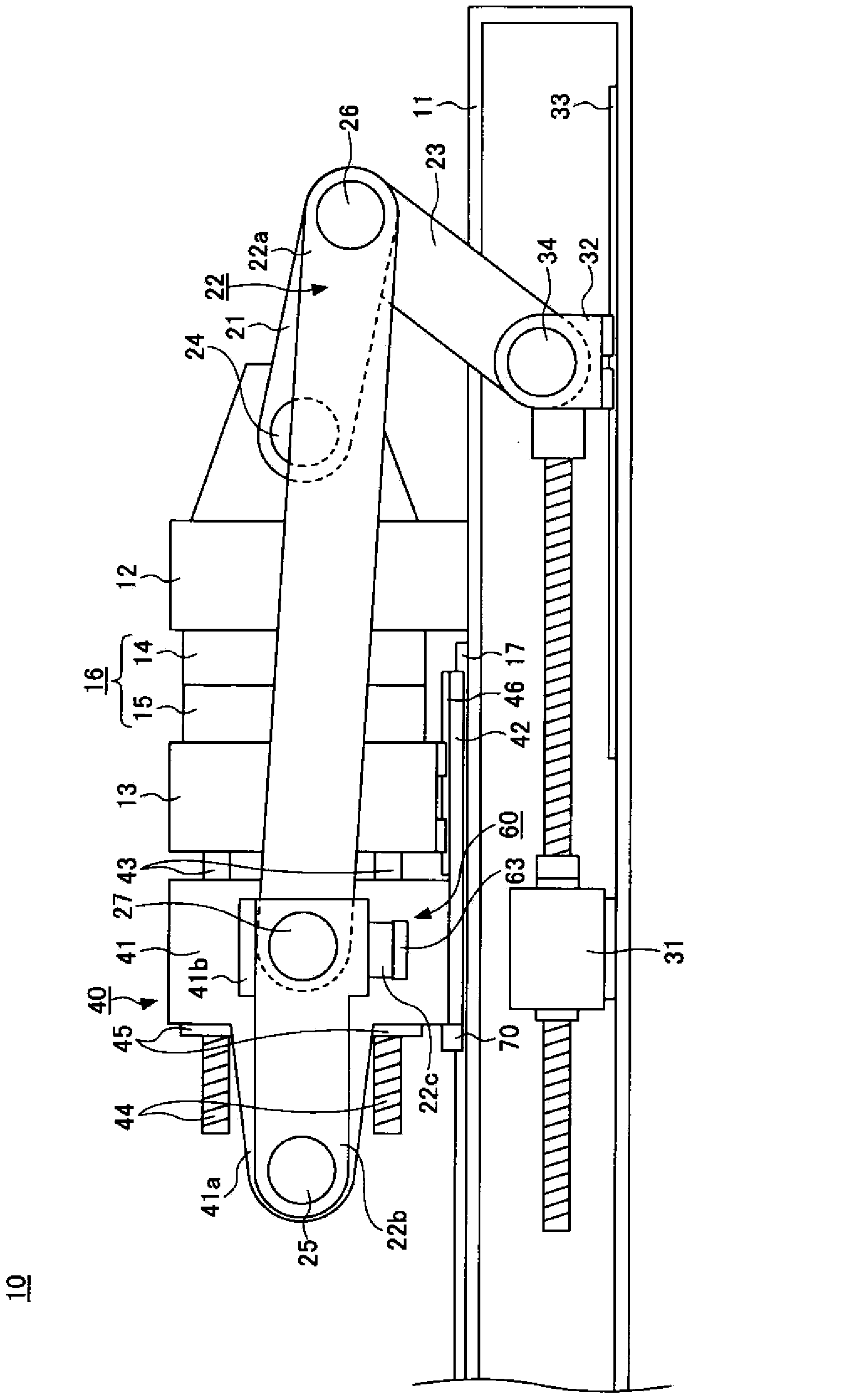
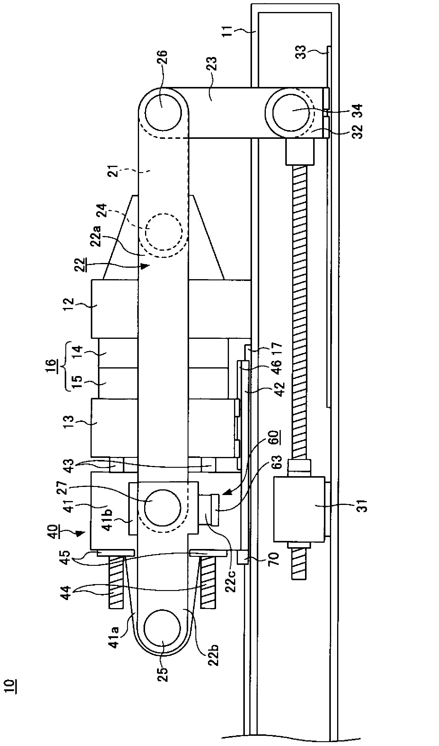
[0019] figure 1 It is a figure which shows the state at the time of completion of mold opening of the injection molding machine concerning 1st Embodiment of this invention. figure 2 It is a figure which shows the state at the time of completion of mold closing of the injection molding machine concerning 1st Embodiment of this invention. image 3 It is a figure which shows the state at the time of completion of mold clamping of the injection molding machine concerning 1st Embodiment of this invention. Figure 4 It is a figure which shows the state at the time of die replacement of the injection molding machine concerning 1st Embodiment of this invention.
[0020] The injection molding machine 10 includes a frame 11 , a fixed platen 12 , a movable platen 13 , a short link 21 , a long link 22 , a push rod 23 , a mold clamping motor 31 , a mold thickness adjustment unit 40 , and a first link lock mechanism 60 And the locking mechanism 70 of the pressing plate.
[0021] The fix...
no. 2 Embodiment approach
[0056] In the first embodiment described above, the support guide 46 supports the movable platen 13 from below, but the present embodiment is different in that the support guide supports the movable platen from the side. Hereinafter, differences will be mainly described.
[0057] Figure 5 It is a figure which shows the mold thickness adjustment part and the movable platen of 2nd Embodiment of this invention.
[0058] The mold thickness adjustment part 140 is formed by, for example, a main body part 141, a support block 142 as a support part for supporting the main body part 141, an adjustment rod 143 connecting the main body part 141 and the movable platen 113 at intervals in the mold opening and closing direction, and An adjustment nut 145 screwed to the screw shaft portion 144 of the adjustment rod 143 , an adjustment motor that rotates the adjustment nut 145 , and the like are configured.
[0059] The main body portion 141 is disposed behind the movable platen 113 . The...
no. 3 Embodiment approach
[0070] In the above-mentioned first embodiment, the support guide 46 that supports the movable platen 13 freely in the mold opening and closing direction is provided on the support block 42, but the difference in this embodiment is that the support guide is provided on the frame. superior. Hereinafter, differences will be mainly described.
[0071] Image 6 It is a figure which shows the die-thickness adjustment part and movable platen which concerns on 3rd Embodiment of this invention.
[0072] The mold thickness adjusting part 240 is formed by, for example, a main body part 241, a support block 242 as a support part for supporting the main body part 241, an adjustment lever 243 connecting the main body part 241 and the movable platen 213 at intervals in the mold opening and closing direction, and a The adjustment nut 245 to which the screw shaft portion 244 of the adjustment rod 243 is screwed, an adjustment motor to rotate the adjustment nut 245 , and the like are configu...
PUM
 Abstract
Description
Claims
Application Information
 - R&D
- Intellectual Property
- Life Sciences
- Materials
- Tech Scout
- Unparalleled Data Quality
- Higher Quality Content
- 60% Fewer Hallucinations
Browse by: Latest US Patents, China's latest patents, Technical Efficacy Thesaurus, Application Domain, Technology Topic, Popular Technical Reports.
© 2025 PatSnap. All rights reserved.Legal|Privacy policy|Modern Slavery Act Transparency Statement|Sitemap|About US| Contact US: help@patsnap.com