
Fault identification method for long-distance UHV AC transmission lines

A technology for UHV AC and transmission lines, which is applied to fault locations, emergency protection circuit devices, electrical components, etc. It can solve problems such as failure to meet the requirements of quick action of relay protection, large data window, extended time, etc., and achieve calculation Fast speed, small amount of calculation, and the effect of improving the speed of movement

Active Publication Date: 2017-02-15
STATE GRID PUTIAN ELECTRIC POWER SUPPLY +3
View PDF5 Cites 0 Cited by
  • Summary
  • Abstract
  • Description
  • Claims
  • Application Information

AI Technical Summary

Problems solved by technology

Some of the transmission line traveling wave differential protection methods even require wavelet transform, which requires a large data window, which prolongs the time for protection to detect faults, and cannot meet the requirements of relay protection for quick action.

Method used


Image

  • Fault identification method for long-distance UHV AC transmission lines
  • Fault identification method for long-distance UHV AC transmission lines
  • Fault identification method for long-distance UHV AC transmission lines

Examples


Embodiment Construction

[0022] The technical solution of the present invention will be described in further detail below according to the accompanying drawings.

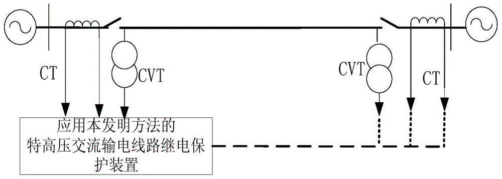
[0023] figure 1 It is a schematic diagram of an UHV AC power transmission system applying the method of the present invention. This embodiment first collects the three-phase voltage traveling wave components and three-phase current traveling wave components at each sampling time of the UHV AC transmission line at the protection installation place of the m substation; collects each sampling of the UHV AC transmission line at the protection installation place of the n substation Three-phase voltage traveling wave component and three-phase current traveling wave component at time.

[0024] The three-phase voltage traveling wave component and the three-phase current traveling wave component at each sampling time of the m and n substation protection installations are converted into 0, α, β mode voltage traveling wave components and 0, α, β mode...


PUM


Abstract

The invention discloses a remote ultra-high voltage alternating-current transmission line fault determination method. The method comprises the steps that voltage and current travelling wave components at each sampling moment at protection installation positions at the two ends of an ultra-high voltage alternating-current transmission line are collected at first, the influence of line losses is calculated, the travelling wave electrical quantity at each sampling moment is utilized for calculating the current travelling wave component at one end of the ultra-high voltage alternating-current transmission line through a prediction algorithm, then a distributed capacitance current along the ultra-high voltage alternating-current transmission line is used as a braking current, the vector sum of the current travelling wave component, obtained through calculation, at one end of the ultra-high voltage alternating-current transmission line and the current travelling wave component, obtained through sampling, at the end of the ultra-high voltage alternating-current transmission line is used as a difference current, and phase splitting is carried out to form main protection of the ultra-high voltage alternating-current transmission line. According to the remote ultra-high voltage alternating-current transmission line fault determination method, the current travelling wave components at each sampling moment does not need to be solved through interpolation operation, the operand of current travelling wave protection is reduced, the movement speed of current travelling wave differential protection is improved, and the remote ultra-high voltage alternating-current transmission line fault determination method is applicable to ultra-high voltage alternating-current transmission line replay protection under different operating environments and circuit parameters.

Description

technical field [0001] The invention relates to the technical field of relay protection of electric power systems, in particular to a method for judging faults of long-distance UHV AC transmission lines. Background technique [0002] Because it is not affected by the system operation mode and grid structure and has a natural phase selection function, the current differential protection has always been the main protection of various voltage levels of transmission lines. In the 220kV and below voltage level transmission lines, because the distributed capacitance current along the transmission line is very small, the distributed capacitance has little influence on the operation performance of the current differential protection. However, the voltage and current transmission of the UHV AC transmission line has an obvious wave process, and the distributed capacitive current along the line is very large. The traditional current differential protection that uses the vector sum of t...

Claims


Application Information

Patent Timeline
Patent Type & Authority Patents(China)
IPC IPC(8): H02H7/26G01R31/08
Inventor 曾惠敏林富洪
Owner STATE GRID PUTIAN ELECTRIC POWER SUPPLY
Learn More