Color filter substrate and curved surface display device
A color filter substrate, lateral width technology, applied in optics, instruments, nonlinear optics, etc., can solve the problem of low aperture ratio of curved displays, and achieve the effect of solving low aperture ratio
- Summary
- Abstract
- Description
- Claims
- Application Information
AI Technical Summary
Problems solved by technology
Method used
Image
Examples
Embodiment 1
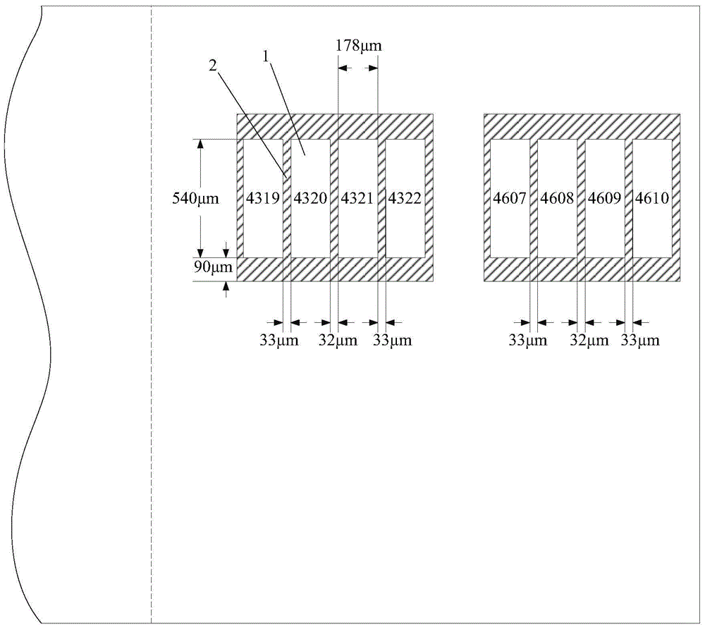
[0027] In this embodiment, a color filter substrate in a 55-inch full high definition (Full High Definition, FHD for short) curved liquid crystal television is taken as an example for illustration. The resolution of a full HD LCD TV is 1920×1080, that is, a total of 1080 rows and 1920 columns of pixel areas, and each pixel area is composed of 3 sub-pixel areas arranged side by side, so there are 5760 columns of sub-pixel areas on the color filter substrate.
[0028] The lateral width of all or part of the black matrix located on both sides of the color filter substrate is smaller than the lateral width of the black matrix located in the middle area of the color filter substrate. The areas on both sides can usually account for 50% to 70% of the total area of the color filter substrate, because in the prior art, due to the offset between the black matrix and the data lines, a total of 50% to 70% of the area on both sides of the curved display will be caused. The aperture rat...
Embodiment 2
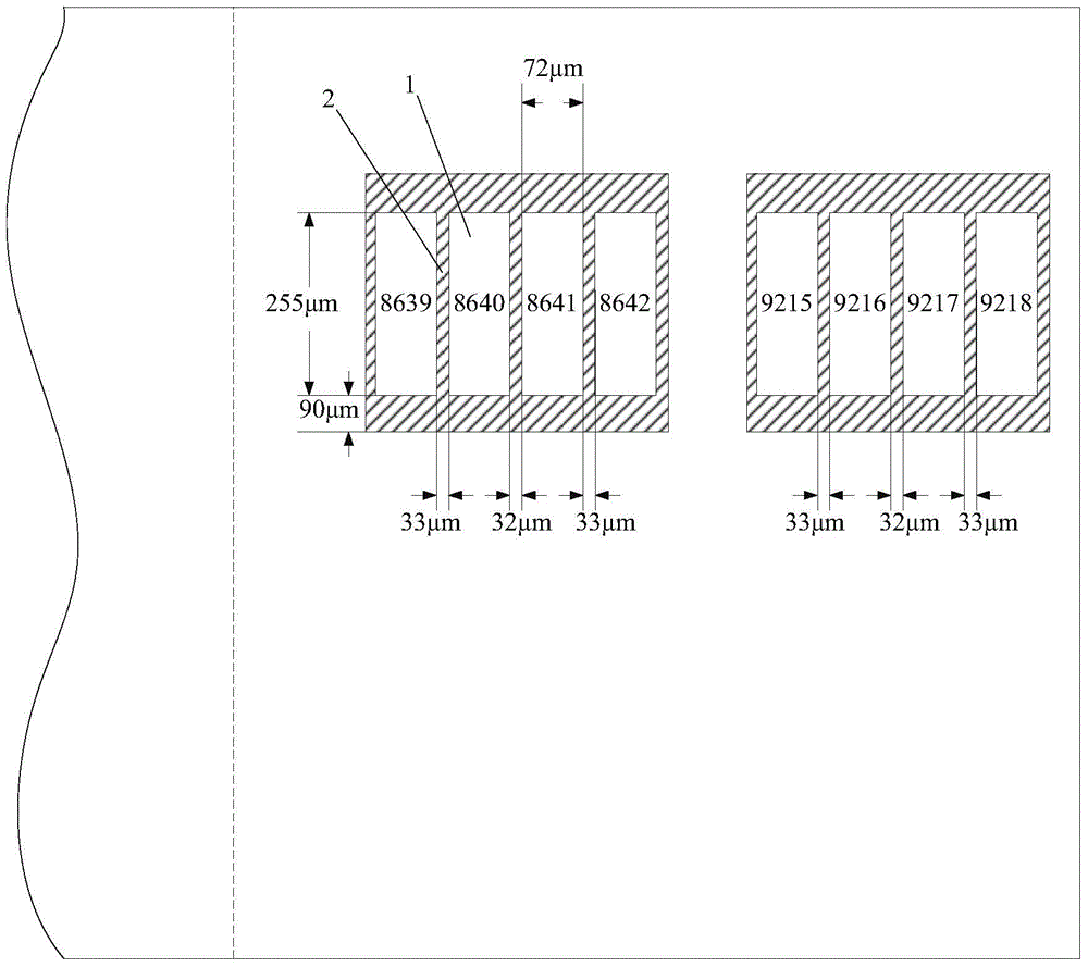
[0038] This embodiment is basically the same as Embodiment 1, except that the color filter substrate provided in this embodiment is a color filter substrate in a 55-inch ultra high definition (Ultra High Definition, UD for short) curved liquid crystal TV. The resolution of ultra-high-definition LCD TV is 3840×2160, that is, there are 3840 rows and 2160 columns of pixel areas in total. Each pixel area is composed of 3 sub-pixel areas arranged side by side, so there are 11520 columns of sub-pixel areas on the color filter substrate.
[0039] Such as figure 2 As shown, in this embodiment, there are 5 black matrixes 2 on the left and right sides each with a lateral width of 32 microns, and they are evenly distributed in the 2880 black matrices 2 on the left and right sides respectively, and the remaining black matrices 2 (including The lateral widths of the black matrix in the middle area and the black matrix in the two side areas are both 33 microns. figure 2 Only the schemati...
Embodiment 3
[0043] An embodiment of the present invention provides a curved display device, which may be a 55-inch full high-definition curved liquid crystal TV, which includes an array substrate and the color filter substrate provided in the first embodiment above.
[0044] The curved display device may also be a 55-inch ultra-high-definition curved liquid crystal TV, which includes an array substrate and the color filter substrate provided in the second embodiment above.
[0045] Of course, the curved display device may also be a curved liquid crystal television of other sizes and models, or other curved display devices.
PUM
| Property | Measurement | Unit |
|---|---|---|
| width | aaaaa | aaaaa |
| width | aaaaa | aaaaa |
| width | aaaaa | aaaaa |
Abstract
Description
Claims
Application Information
 - R&D
- Intellectual Property
- Life Sciences
- Materials
- Tech Scout
- Unparalleled Data Quality
- Higher Quality Content
- 60% Fewer Hallucinations
Browse by: Latest US Patents, China's latest patents, Technical Efficacy Thesaurus, Application Domain, Technology Topic, Popular Technical Reports.
© 2025 PatSnap. All rights reserved.Legal|Privacy policy|Modern Slavery Act Transparency Statement|Sitemap|About US| Contact US: help@patsnap.com


