Eureka AIR delivers breakthrough ideas for toughest innovation challenges, trusted by R&D personnel around the world.

Terrace flatly-buried type underground nuclear power station

A technology of nuclear power plants and terraces, applied in the field of nuclear power, can solve the problems that the overall layout of ground nuclear power plants cannot meet the needs of building underground nuclear power plants, the number of buildings is large, and the differences are large, so as to reduce the difficulty of technology research and development, improve engineering economy, and avoid supply interruptions Effect

Active Publication Date: 2014-09-24
CHANGJIANG SURVEY PLANNING DESIGN & RES +1
View PDF5 Cites 8 Cited by
  • Summary
  • Abstract
  • Description
  • Claims
  • Application Information

AI Technical Summary

Problems solved by technology

However, the excavation of underground caverns is generally selected in mountainous or hilly terrain environments, and the construction environment is quite different from that of ground nuclear power plants; and the nuclear islands of ground nuclear power plants and conventional islands are arranged in close proximity, with many buildings and large sizes. Space technology is difficult to accommodate all the buildings of the nuclear island in a single artificial underground cavern, and the overall layout of the ground nuclear power plant cannot meet the needs of the construction of an underground nuclear power plant

Method used


Image

  • Terrace flatly-buried type underground nuclear power station
  • Terrace flatly-buried type underground nuclear power station
  • Terrace flatly-buried type underground nuclear power station

Examples


Embodiment Construction

[0025] The present invention will be described in further detail below in conjunction with the accompanying drawings and embodiments, but these embodiments should not be construed as limiting the present invention.

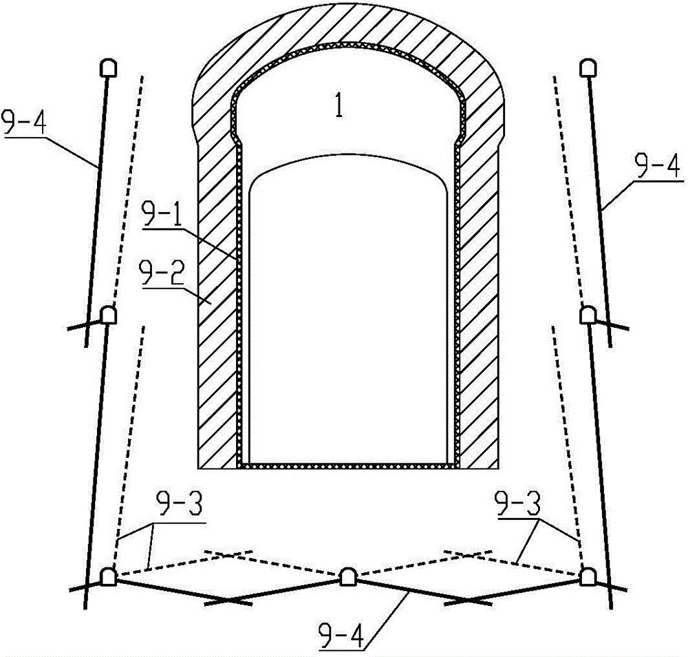
[0026] refer to figure 1 , figure 2 and image 3 , the present invention is a terraced buried underground nuclear power plant, including a nuclear island and a conventional island. The nuclear-related buildings of the nuclear island are placed in the cavern group of the nuclear island of the mountain A, and the conventional island is placed in the first conventional island area C and the second conventional island. In area D, the first conventional island area C is located on the terraced platform E on the upper part of the mountain A, the second conventional island area D is located on the outer ground platform B, and the nuclear island caverns are buried in the mountain A relative to the second conventional island D ,like figure 1 shown.

[0027] The nuclea...


PUM


Abstract

The invention discloses a terrace flatly-buried type underground nuclear power station which comprises a nuclear island and a conventional island. Nuclear-related buildings of the nuclear island are arranged in a nuclear island cavern group of a mountain, the conventional island is arranged on a first conventional island area and a second conventional island area, the first conventional island area is located on a terrace platform on the upper portion of a side slope of the mountain, the second conventional island area is located on a ground platform on the outer side of the side slope, and the nuclear island cavern group is flatly buried in the side slope of the mountain relative to the second conventional island area. The terrace flatly-buried type underground nuclear power station is suitable for the terrain environment with the large platforms on the outer side and the upper portion of the side slope of the mountain or the terrain environment with the large platforms easily formed on the outer side and the upper portion of the side slope of the mountain in a hand excavation mode, and feasible general arrangement is provided for the underground nuclear power station. Compared with a ground nuclear power station, a main process system does not need to be greatly adjusted, and the technical development difficulty of the underground nuclear power station is lowered. Nuclear island plants are arranged in different underground caverns, and it can be guaranteed that the existing underground engineering technology meets the requirement that the nuclear-related buildings of the nuclear power station are arranged underground.

Description

technical field [0001] The invention relates to nuclear power technology, in particular to a terrace-buried underground nuclear power plant. Background technique [0002] At present, large-scale commercial nuclear power plants are arranged on the ground, and the power of a single reactor is generally above 600MW. The building mainly includes two parts: the nuclear island (including the reactor device and the primary circuit system) and the conventional island (including the turbogenerator system, cooling tower, etc. auxiliary equipment, etc.). The Chernobyl nuclear accident in the former Soviet Union, the Three Mile Island nuclear accident in the United States, and the Fukushima nuclear accident in Japan have shown that the existing ground nuclear power plants are not enough to effectively prevent and control nuclear leakage and ensure nuclear safety under extreme accident conditions. For this reason, some scholars at home and abroad have proposed to build nuclear-related b...

Claims


Application Information

Patent Timeline
IPC IPC(8): G21D1/02
CPCY02E30/40Y02E30/00
Inventor 钮新强赵鑫周述达韩前龙杜申伟胡建华张存慧程淑艳刘海波喻飞张文其李庆任云张凯余小权
Owner CHANGJIANG SURVEY PLANNING DESIGN & RES
Why Eureka
Eureka Blog
Learn More