Torque adjusting device, movement and mechanical clock
An adjustment device, a mechanical technology, applied in mechanically driven clocks, clocks, gear mechanisms, etc., can solve the problems of difficult to set the winding amount of the scroll spring 18, poor volume efficiency, etc.
- Summary
- Abstract
- Description
- Claims
- Application Information
AI Technical Summary
Problems solved by technology
Method used
Image
Examples
no. 1 Embodiment approach
[0057] (First Embodiment, Torque Adjusting Device 6 )
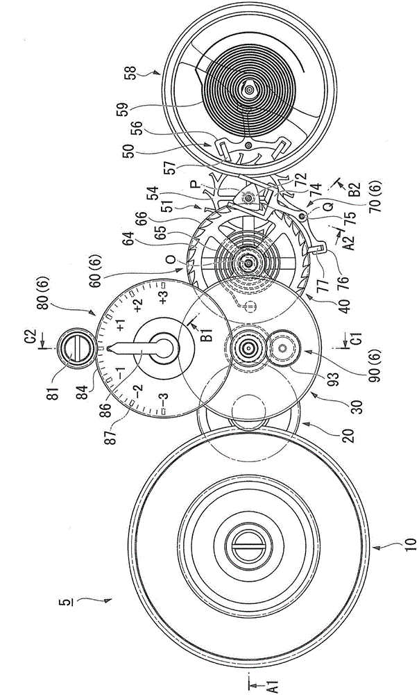
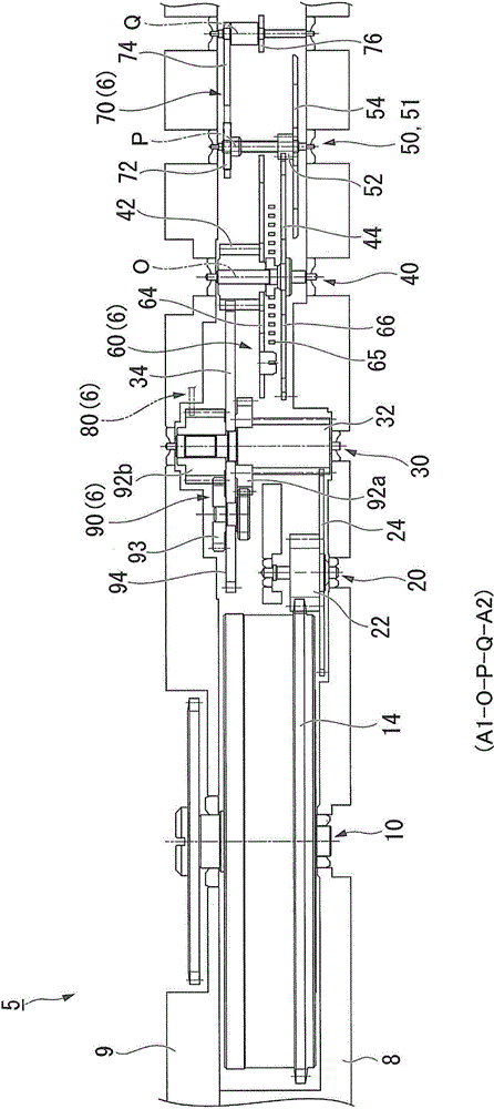
[0058] Such as image 3 As shown, if the operating torque transmitted from the barrel 10 to the escapement 50 changes with the unwinding of the mainspring, the swing angle of the balance wheel changes, and the rate of change of the timepiece changes. In order to suppress such fluctuations in operating torque, the movement 5 includes a torque adjustment device 6 in which a subspring (torque adjustment spring) 65 is incorporated into a wheel train from the barrel 10 to the escapement 50 .
[0059] The torque adjustment device 6 is equipped with: a torque adjustment device main body 60, which is equipped with a secondary spring 65; a torque adjustment escapement 70, which controls the movement of the torque adjustment device main body 60; a tightening amount adjustment mechanism 80, which adjusts The winding amount of the subspring 65 ; and the power switching mechanism (planetary gear mechanism 90 ), which is assembled in ...
no. 2 Embodiment approach )
[0113] Figure 9 It is an explanatory diagram of the torque adjustment device 206 of the second embodiment, and is equivalent to figure 2 Side sectional view of a portion of the line A1-O-P-Q-A2. in the aforementioned image 3 In the torque adjusting device 6 according to the first embodiment shown, the planetary gear mechanism 90 is incorporated in the third wheel 30, but Figure 9 The torque adjustment device 206 of the second embodiment shown is different in that a planetary gear mechanism 290 is incorporated into the fourth wheel 40 . In addition, the detailed description of the part of the same structure as 1st Embodiment is abbreviate|omitted.
[0114] in the aforementioned image 3 In the illustrated first embodiment, the torque adjustment device main body 60 including the ratchet 64 , the subspring 65 , and the output gear 66 is assembled in the fourth wheel 40 . The torque adjustment device main body 60 may be assembled in a part other than the fourth wheel 40 ,...
no. 3 Embodiment approach )
[0128] Figure 10 It is an explanatory diagram of the torque adjustment device 306 of the third embodiment, and is a plan view excluding the wheel train support plate on the surface side of the movement. In addition, in Figure 10 The illustration of the bottom plate and the wheel train support plate is omitted in . in the aforementioned figure 2 In the torque adjusting device 6 according to the first embodiment shown, the torque adjusting device main body 60 is provided with a ratchet 64, but Figure 10 The torque adjustment device 306 of the third embodiment shown is different in that a torque adjustment device main body 360 includes a flywheel 364 . In addition, the detailed description of the part of the same structure as 1st Embodiment is abbreviate|omitted.
[0129] Such as Figure 10 As shown, the torque adjustment device main body 360 of the third embodiment includes: a subspring (spring for torque adjustment) 365; The outer peripheral end (first end) is connect...
PUM
 Abstract
Description
Claims
Application Information
 - R&D
- Intellectual Property
- Life Sciences
- Materials
- Tech Scout
- Unparalleled Data Quality
- Higher Quality Content
- 60% Fewer Hallucinations
Browse by: Latest US Patents, China's latest patents, Technical Efficacy Thesaurus, Application Domain, Technology Topic, Popular Technical Reports.
© 2025 PatSnap. All rights reserved.Legal|Privacy policy|Modern Slavery Act Transparency Statement|Sitemap|About US| Contact US: help@patsnap.com


