
Quantity control valve and high-pressure pump with quantity control valve

A technology for controlling valves and high-pressure pumps, which is applied in the field of high-pressure pumps to achieve the effects of reducing mechanical load, reducing rebound speed, and reducing electrical power loss

Active Publication Date: 2014-08-27
ROBERT BOSCH GMBH
View PDF10 Cites 3 Cited by
  • Summary
  • Abstract
  • Description
  • Claims
  • Application Information

AI Technical Summary

Problems solved by technology

[0005] The problem underlying the invention is solved by a quantity control valve according to claim 1

Method used


Image

  • Quantity control valve and high-pressure pump with quantity control valve
  • Quantity control valve and high-pressure pump with quantity control valve
  • Quantity control valve and high-pressure pump with quantity control valve

Examples


Embodiment Construction

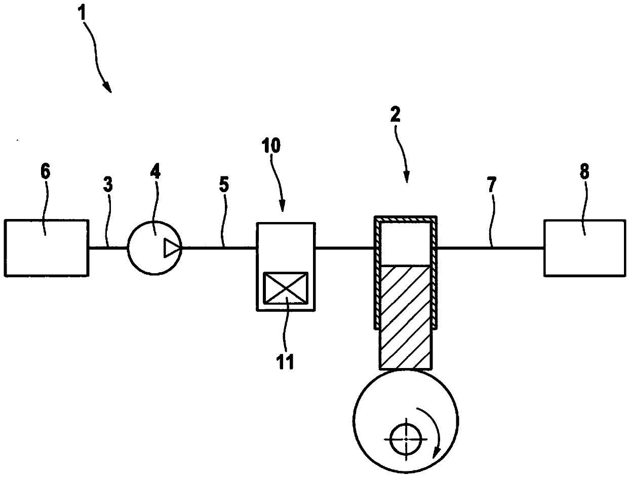
[0026] figure 1 A fuel system 1 of an internal combustion engine is shown in a very simplified illustration. A high-pressure pump 2 , not explained in detail, which is designed as a piston pump, is connected upstream via a suction line 3 , a prefeed pump 4 and a low-pressure line 5 to a fuel tank 6 . Downstream, a high-pressure accumulator 8 (“common rail”) is connected via a high-pressure line 7 to the high-pressure pump 2 . A quantity control valve 10 with electromagnetic actuation (hereinafter referred to as actuator 11 ) is arranged hydraulically between low-pressure line 5 and high-pressure pump 2 and forms an inlet valve for high-pressure pump 2 . Other components, such as the discharge valve of the high-pressure pump 2 figure 1 not shown in It goes without saying that the volume control valve can be integrated into the high-pressure pump 2 .

[0027] When the fuel system 1 is in operation, the prefeed pump 4 conveys fuel from the fuel tank 6 into the low-pressure li...


PUM


Abstract

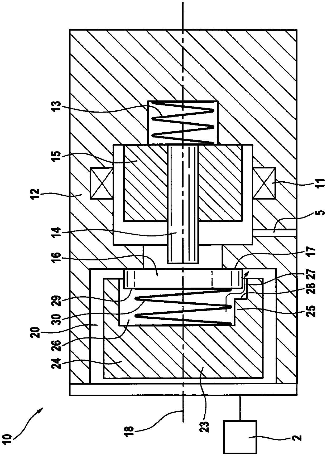
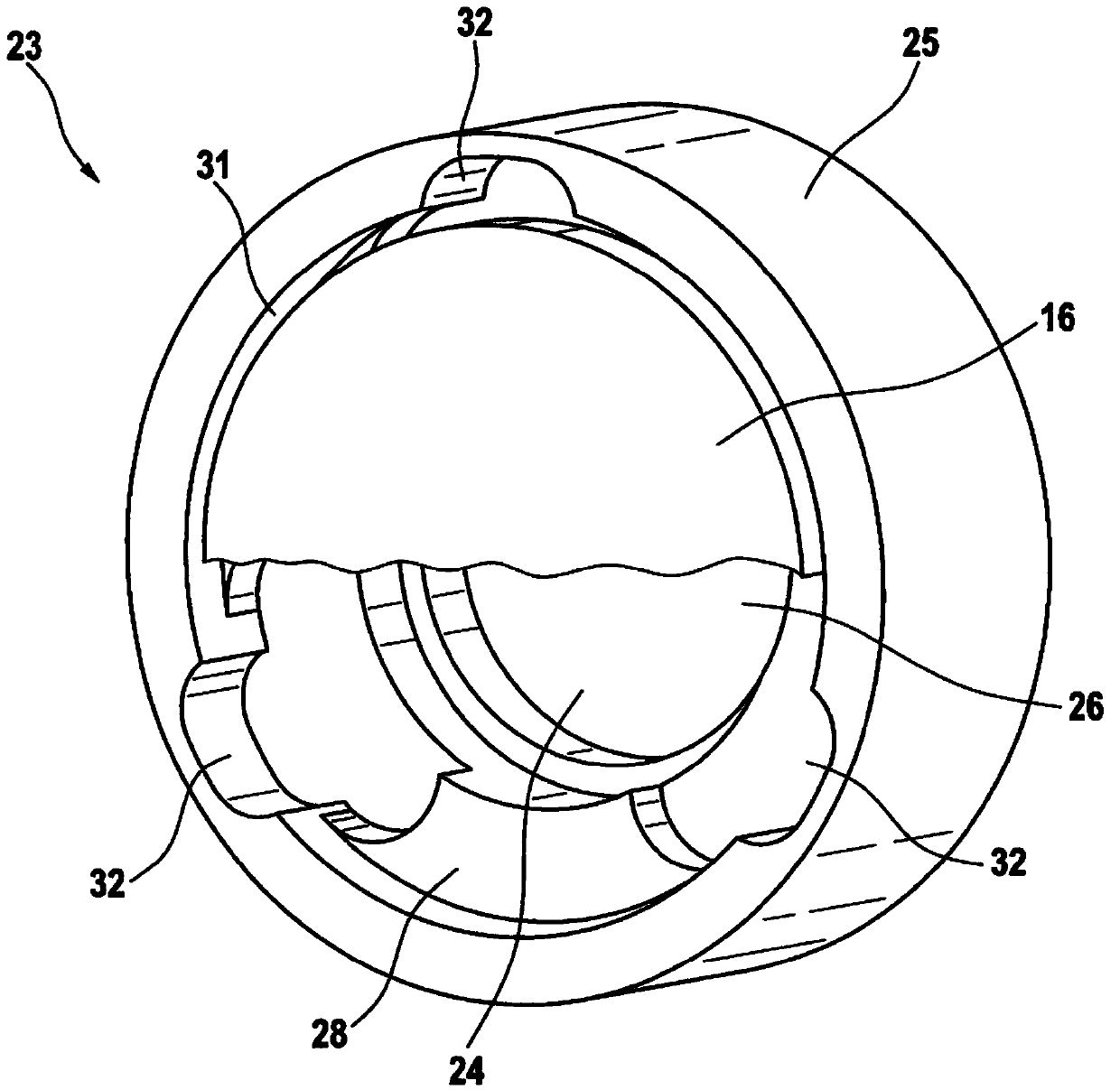
A quantity control valve (10), in particular for metering a fluid for a downstream high-pressure pump (2), with an axially movable valve needle (14) and a valve element (16) that can be impinged upon by the valve needle (14) in an opening direction, wherein the valve element (16) delimits a damping chamber (26), wherein an annular gap (31) with at least one protrusion (32) is present between a wall (25) of the damping chamber (26) and the valve element (16).

Description

technical field [0001] The invention relates to a quantity control valve according to the preamble of claim 1 and a high-pressure pump with a quantity control valve according to independent claim 10 . Background technique [0002] A quantity control valve for a downstream high-pressure pump is disclosed, in particular for dosing fluids. For example, it is used in common rail fuel systems of motor vehicles as a quantity control valve in order to control the flow of fuel fed into the common rail by a high-pressure delivery pump. Such quantity control valves can be actuated electromagnetically. The volume control valve includes a needle-armature combination. The electromagnet and spring, which are part of the needle-armature assembly, act on the valve element of the volume control valve. The impingement of the needle-armature assembly into the open or closed end position of the quantity control valve leads, especially at low rotational speeds, to an oscillation excitation wh...

Claims


Application Information

Patent Timeline
Patent Type & Authority Applications(China)
IPC IPC(8): F02M59/36
CPCF02M2200/28F02M59/367Y10T137/85986F02M2200/304F16K31/0689
Inventor R·维尔姆斯M·梅斯D·布伦纳
Owner ROBERT BOSCH GMBH
Learn More