
A storage battery discharge instrument and its discharge current control method

A discharge current and storage battery technology, which is applied in the field of battery capacity test tools, can solve problems such as increased labor intensity, performance degradation, and increased measurement errors, and achieves improved accuracy and precision, simplified control circuits, and stable discharge current Effect

Active Publication Date: 2017-03-22
LUOHE POWER SUPPLY OF HENAN ELECTRIC POWER CORP
View PDF10 Cites 0 Cited by
  • Summary
  • Abstract
  • Description
  • Claims
  • Application Information

AI Technical Summary

Problems solved by technology

The 220kV substation and some 110kV substations use two sets of batteries. When the batteries are inspected, the two sets of DC systems must be connected in parallel, and then one set of batteries should be separated from the DC system. The 10-hour discharge rate I 10 Discharge, when setting the current, because the instrument is not accurate enough, it is often necessary to increase or decrease it based on experience. Less discharge has been carried out, and with the progress of discharge, the voltage of the storage battery has been dropping, and its discharge current is also changing, and then the discharge current I 10fd multiplied by the discharge time t fd Calculating the discharge capacity is not accurate enough, resulting in large errors and even misjudgments
The load current often has certain fluctuations and is not stable enough. The discharge current after the discharge instrument is set is constant.
Due to the fluctuation of the load current, this will cause the battery to discharge more or less, resulting in increased measurement errors, and sometimes qualified batteries will be misjudged as unqualified batteries
[0005] In addition, the heating element of the current discharge instrument on the market is a ceramic resistor. With the operation of the equipment, the internal heating element is continuously oxidized, and the performance is degraded. It is necessary to adjust the settings again, resulting in inaccurate measurement and increased labor intensity, etc.
[0006] All of the above reasons lead to large errors in the easy test of the battery, which seriously affects the accuracy of the test results and the judgment of the battery performance.

Method used


Image

  • A storage battery discharge instrument and its discharge current control method

Examples


Embodiment 1

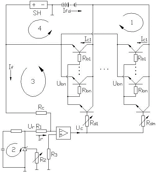
[0028] A battery discharging instrument includes a discharge unit 4 and a set current unit 2 connected to the discharge unit 4, and an automatic adjustment unit 3 is provided between the set current unit 2 and the discharge unit 4. The discharge unit 4 includes 8 sub-discharge units 1 connected in parallel, each sub-discharge unit 1 includes 8 series-connected GTR transistors, and the base of each GTR transistor is connected in series with a resistance R b , The resistor Rb is used to improve the current balance of the emitter; each sub-discharge unit 1 is provided with a preamplifier module and a resistor R connected in series with the preamplifier module d , The preamplifier module can use the simplest amplifier tube or a conventional preamplifier circuit. By selecting the sub-discharge unit and the pre-amplifier tube, or the sub-discharge unit and the pre-amplifier circuit, the amplification factor The total current of each sub-discharge unit tends to be the same, which facili...

Embodiment 2

[0031] The difference between this embodiment and the first embodiment is that the eight parallel sub-discharge units 1 respectively encapsulate a temperature sensor and a heat sink, and are controlled by the same controller. It can effectively improve the heat dissipation efficiency, avoid unnecessary heat dissipation, keep each sub-discharge unit at a relatively constant temperature, ensure the stable performance of each sub-discharge unit, and reduce current deviation.

Embodiment 4

[0033] A method for automatically regulating the discharge current of the battery discharging instrument in the above-mentioned embodiment includes the following steps:

[0034] a) Preset the discharge current by setting the current unit 2 to obtain the set discharge current I r ;

[0035] b) During discharge detection, the automatic adjustment unit 3 obtains the actual discharge current I of the battery through the shunt SH fd ;

[0036] c) The operational amplifier module of the automatic adjustment unit 3 compares the actual discharge current I fd And set discharge current I r the size of:

[0037] When I fd =I r When, the operational amplifier module does not output;

[0038] When I fd > I r When, the operational amplifier module outputs a current-reducing regulated current signal to the pre-amplifier module;

[0039] When I fd r When, the operational amplifier module outputs an adjusted current signal for increasing the current to the pre-amplifier module;

[0040] d) After the ...


PUM


Abstract

The invention discloses a storage battery discharging instrument which comprises a discharging unit and a current setting unit. An automatic adjusting unit is arranged between the discharging unit and the current setting unit. The automatic adjusting unit is arranged between the discharging unit and the current setting unit, the automatic adjusting unit is used for collecting discharging currents in the discharging unit, the discharging currents are compared with currents in the current setting unit, so that the currents of the discharging unit are adjusted in real time, and regulating of the discharging currents in the discharging unit is achieved. Thus, the discharging currents are stable and accurate, the accuracy and precision of an energy storing test of a storage battery are improved, adjusting is automatic, the storage battery discharging instrument is easy and convenient to operate, and the labor intensity of operating workers is greatly lowered.

Description

Technical field [0001] The invention relates to a battery capacity test tool, in particular to a battery discharge meter and a discharge current control method of the discharge meter. Background technique [0002] At present, the DC operating power supply used in power plants and substations to store electrical energy can be regarded as an independent power supply that has nothing to do with the primary system of power plants and substations, which can simplify the power supply structure for operation and protection. It appears in power plants and substations. In the case of failure or even the complete disappearance of the AC power supply, the battery DC system can still work reliably, effectively ensuring the power supply reliability of the DC system. In addition, because the battery voltage is stable and the capacity is large, it can provide a large inrush current when the circuit breaker is closed, and can be used as a backup power source for accident safety loads. [0003] Th...

Claims


Application Information

Patent Timeline
Patent Type & Authority Patents(China)
IPC IPC(8): G01R31/36G05F1/613G01R1/00
Inventor 李亮赵永浩韩源姚艳霞陶凤源任永杰李帅刘海燕王建军胡兆宏付建朝
Owner LUOHE POWER SUPPLY OF HENAN ELECTRIC POWER CORP
Learn More