Optical element, window material, fitting, solar shading device, and building

一种光学体、建筑物的技术,应用在光学体,窗材料,日射遮蔽装置及建筑物,隔断构件领域,能够解决温度上升、草坪生长等问题,达到抑制膜厚不均匀的效果

Active Publication Date: 2014-08-13
DEXERIALS CORP
View PDF4 Cites 8 Cited by
  • Summary
  • Abstract
  • Description
  • Claims
  • Application Information

AI Technical Summary

Problems solved by technology

As a result, in the vicinity of buildings where such reflective layers are attached to the entire windows, local temperature rises, the heat island becomes more serious in urban areas, and problems such as lawn growth on the irradiated surface that only reflects light arise.

Method used


Image

  • Optical element, window material, fitting, solar shading device, and building
  • Optical element, window material, fitting, solar shading device, and building
  • Optical element, window material, fitting, solar shading device, and building

Examples


Embodiment approach

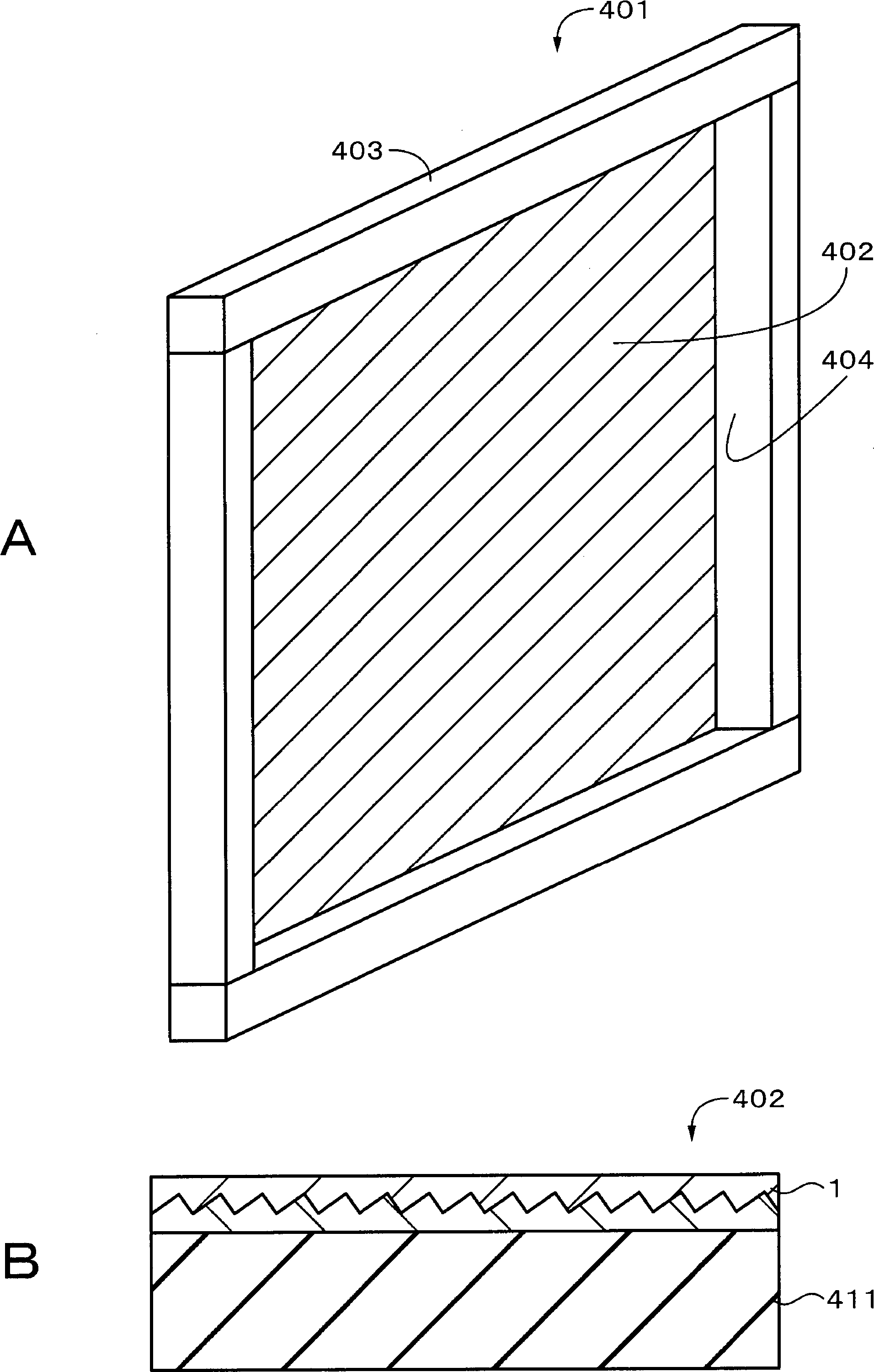
[0061] 7. Seventh Embodiment (Example of Applying an Optical Film to a Partition Member)

no. 1 Embodiment approach >

[0063] [Structure of Optical Film]

[0064] figure 1 A is a cross-sectional view showing an example of the configuration of the optical film according to the first embodiment. figure 1 B is a cross-sectional view illustrating an example in which the optical film according to the first embodiment is adhered to an attachment object. The optical film 1 as an optical body is an optical film having so-called retroreflection performance. like figure 1 As shown in A, this optical film 1 includes an optical layer 2 having a concavo-convex interface inside, and a wavelength selective reflection layer 3 provided on the interface of the optical layer 2 . The optical layer 2 includes a first optical layer 4 having a concave-convex first surface, and a second optical layer 5 having a concave-convex second surface. The interface inside the optical layer is formed by the concavo-convex first surface and the second surface arranged to face each other. Specifically, the optical film 1 inc...

no. 2 Embodiment approach >

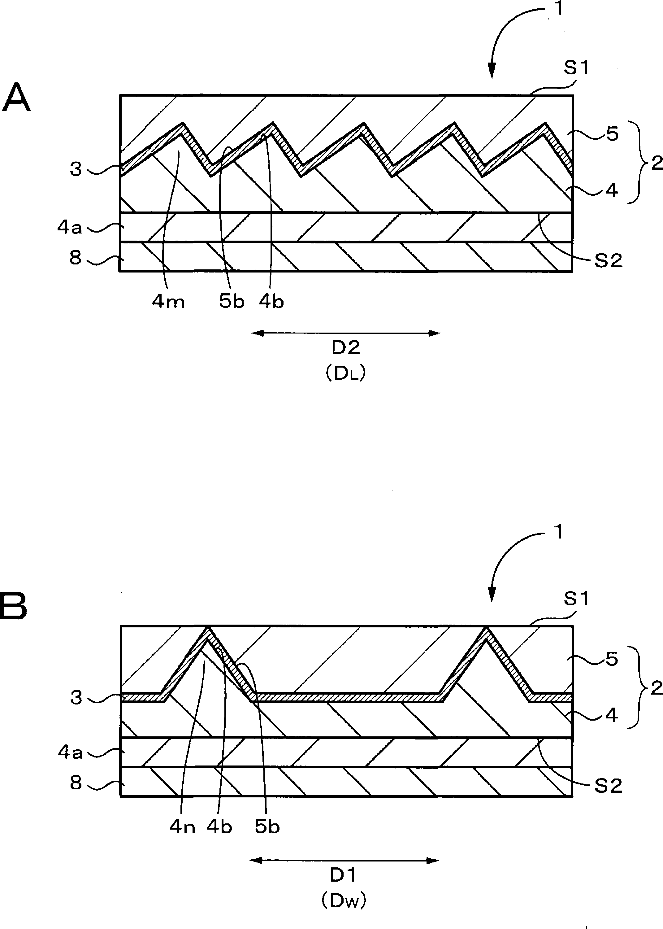
[0208] Figure 20 It is a plan view which shows an example of the shape of the uneven|corrugated surface of the 1st optical layer of the optical film which concerns on 2nd Embodiment. In the second embodiment, two directions obliquely intersecting in the concave-convex surface of the first optical layer 4 are referred to as a first direction D1 and a second direction D2. When the first optical layer 4 has a rectangular shape having two sets of sides facing each other, it is preferable that the first direction D1 is the extending direction of one set of the two sets of sides. The first optical layer 4 has a short-side direction D W and the long side direction D L In the case of a strip shape or a rectangular shape, it is preferable that the first direction D1 is the short side direction D of the first optical layer 4 W .

[0209] The optical film related to the second embodiment is as follows Figure 20 As shown, the first embodiment differs from the first embodiment in th...


PUM

PropertyMeasurementUnit
reflectivityaaaaaaaaaa
visible light transmittanceaaaaaaaaaa
hazeaaaaaaaaaa

Abstract

An optical element is provided with an optical layer in which a concavo-convex surface is formed on the surface thereof, and a wavelength-selective reflection layer formed on the concavo-convex surface. The wavelength-selective reflection layer directionally reflects light having a specific wavelength band selectively, while transmitting light having wavelength bands other than the specific wavelength band. The concavo-convex surface is provided with a plurality of first structural elements that are extended in a first direction within the surface of the optical layer and a plurality of second structural elements that are extended in a second direction within the surface of the optical layer, and placed to be spaced apart from each other, with the first direction and the second direction intersecting with each other.

Description

technical field [0001] The technology relates to optical bodies, window materials, partition members, solar shading devices and buildings. More specifically, it relates to an optical body that directionally reflects incident light. Background technique [0002] From the viewpoint of reducing the air-conditioning load, window films for shielding sunlight are commercially available. As a technique for shielding sunlight, there are commercially available a film that absorbs sunlight and a film that reflects sunlight. However, in the case of the former film, the film that absorbs sunlight heats up, and the peripheral part of the window called the peripheral area heats up. . Regarding the latter, many technologies using optical multilayer films, metal-containing films, transparent conductive films, and the like have been disclosed as reflective layers (for example, refer to Patent Document 1). [0003] However, since such a reflective layer is arranged on a flat window glass, ...

Claims


Application Information

Patent Timeline
Patent Type & Authority Applications(China)
IPC IPC(8): G02B5/26B32B7/02E06B9/24G02B5/08G02B5/10
CPCE06B9/386B32B7/02E06B9/24E06B9/42G02B5/10G02B5/26E06B2009/2417G02B5/045
Inventor 长浜勉涉谷笃史
Owner DEXERIALS CORP
Why Eureka
Try Eureka