
Composite material structure of scaffold

A composite material and scaffolding technology, applied in the direction of building structure support, building structure support, scaffolding connection, etc., can solve the problems of inconvenient assembly and transportation, increased overall quality, safety concerns, etc., and achieve the goal of increasing convenience and strength Effect

Inactive Publication Date: 2014-07-23
克威实业股份有限公司
View PDF6 Cites 3 Cited by
  • Summary
  • Abstract
  • Description
  • Claims
  • Application Information

AI Technical Summary

Problems solved by technology

[0002] A scaffolding structure, the scaffolding is composed of a number of uprights and cross bars, wherein, the uprights are fixedly fitted with a coupling disc, and the coupling disc is sequentially pierced with several Assembling through holes, and the crossbar is equipped with a group joint at the end. The group joint is provided with a combination slot in the horizontal direction, and a locking slot is provided in the longitudinal direction through the combination slot. The cross bar is combined with the group joint. The slotted ferrule is fitted on the combination plate, and the locking groove is connected with the assembly hole correspondingly, and then a bolt is provided to connect and fix, so that the upright column and the horizontal bar are connected and fixed through the combination plate and the assembly joint, and the completion is complete. It is a scaffold structure. However, it is known that the combination plate and the assembly joint of the scaffold structure are integrally formed of rigid metal materials. Although it has the strength of the structural composition, the overall quality is also increased, causing inconvenience for the user to assemble and transport. , the assembly also has shortcomings in assembly due to the heavy quality, which is likely to cause safety concerns

Method used


Image

  • Composite material structure of scaffold
  • Composite material structure of scaffold
  • Composite material structure of scaffold

Examples


Embodiment Construction

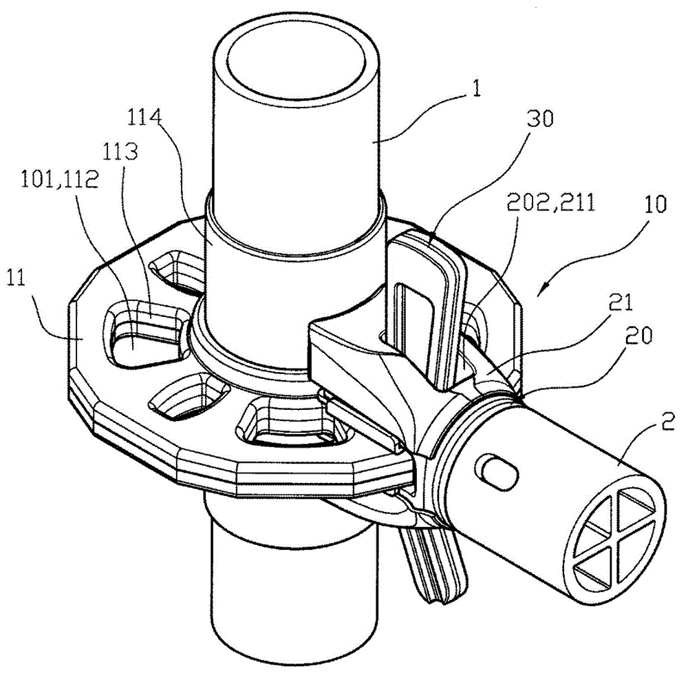
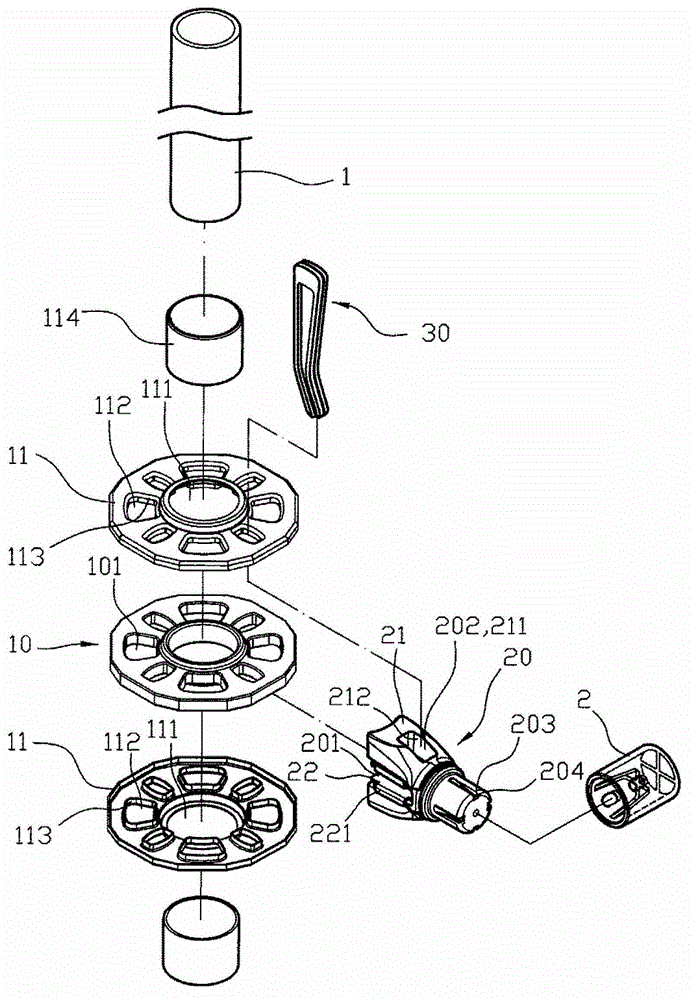
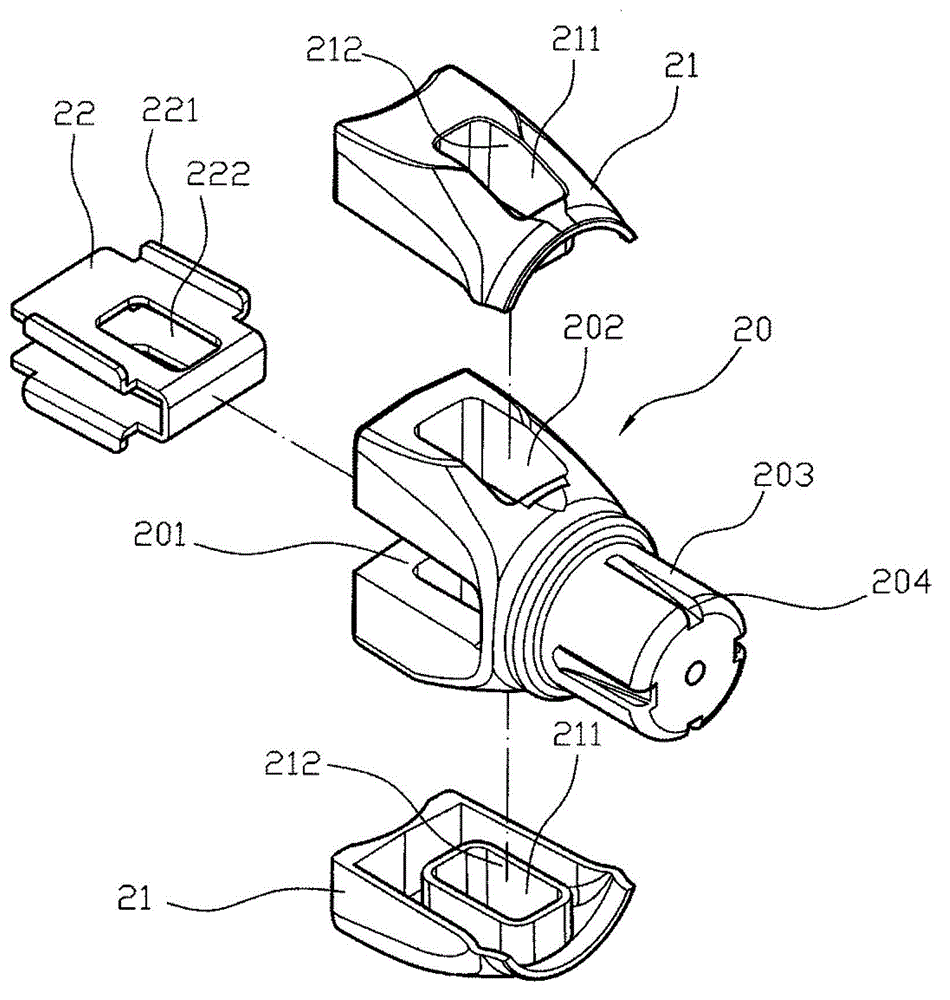
[0018] First, please see figure 1 , figure 2 , image 3 As shown, a composite material structure of a scaffold, the scaffold is composed of a plurality of uprights 1 and crossbars 2, wherein the uprights 1 are fixedly provided with a coupling plate 10 through a sleeve, and the coupling plate 10 is that a number of assembly through holes 101 are sequentially pierced on the peripheral surface, and the cross bar 2 is equipped with assembly joints 20 at the ends. 201 is provided with a snap-through groove 202, and its cross bar 2 is clipped on the joint plate 10 of the column 1 by using the combined slot 201 of the assembly joint 20, and the snap-through slot 202 is communicated with the assembly through-hole 101 correspondingly, and then Provide a bolt 30 to be inserted and fixed, so that the column 1 and the cross bar 2 are connected and fixed to each other through the joint plate 10 and the assembly joint 20, and a scaffold structure is completed, wherein the joint plate 10 ...


PUM


Abstract

Disclosed is a composite material structure of a scaffold. The scaffold is formed by assembling a plurality of vertical columns and transverse rods, the transverse rods are connected to combination discs of the vertical columns in a sleeved and clamped mode through combined open grooves of assembling connectors to form a scaffold structure, the combined discs and the assembling connectors are formed by light metal materials integrally, the surfaces of the combined discs and the assembling connectors are covered with reinforcing shells and reinforcing outer covers of different materials, and reinforcing embedded plates are embedded into the combined open grooves of the assembling connectors. Therefore, through the light metal materials of the combined discs and the assembling connectors, use convenience is achieved, convenience for structural carrying and use safety are increased, the advantage that the scaffold structure can be assembled fast is achieved, the structural rigidity of the combined discs and the assembling connectors is kept through composite materials formed by the reinforcing shells, the reinforcing outer covers and the reinforcing embedded plates, and therefore the strength of structure components is increased.

Description

technical field [0001] The invention relates to a scaffold structure, especially a scaffold composite material structure. Background technique [0002] A scaffolding structure, the scaffolding is composed of a number of uprights and cross bars, wherein, the uprights are fixedly fitted with a coupling disc, and the coupling disc is sequentially pierced with several Assembling through holes, and the crossbar is equipped with a group joint at the end. The group joint is provided with a combination slot in the horizontal direction, and a locking slot is provided in the longitudinal direction through the combination slot. The cross bar is combined with the group joint. The slotted ferrule is fitted on the combination plate, and the locking groove is connected with the assembly hole correspondingly, and then a bolt is provided to connect and fix, so that the upright column and the horizontal bar are connected and fixed through the combination plate and the assembly joint, and the ...

Claims


Application Information

Patent Timeline
IPC IPC(8): E04G7/22
Inventor 宁致平蔡瑞云
Owner 克威实业股份有限公司
Learn More