Seat armrest support structure

A technology of armrest support and seat frame, which is applied in the direction of armrests, vehicle seats, special positions of vehicles, etc., and can solve problems such as safety problems, fracture of rotating shafts or guide pillars, etc., to ensure safe use, avoid damage, and ensure The effect of stability

Active Publication Date: 2014-07-23
GREAT WALL MOTOR CO LTD
View PDF6 Cites 5 Cited by
  • Summary
  • Abstract
  • Description
  • Claims
  • Application Information

AI Technical Summary

Problems solved by technology

The handrails in the above two technical solutions can have better functional effects on the basis of realizing their basic functions, but the above two kinds of handrails are guide posts (pins) and arc grooves (slides) when deployed. Direct rigid contact, relying on the guide column (pin) to provide support to the armrest, which will not affect the connection between the armrest and the seat and the supporting structure when the armrest is not under a large pressure, but in actual use It often happens that the handrail is used as a fulcrum artificially to make it bear a large pressure. At this time, the large pressure will generate a large shear moment on the handrail connection and supporting structure, and it is easy to make the rotation shaft or guide post (pin) of the handrail The child) breaks, and this action process is difficult to find, so this structural deficiency will bring problems to the safety of the handrail during use

Method used


Image

  • Seat armrest support structure
  • Seat armrest support structure
  • Seat armrest support structure

Examples


Embodiment 1

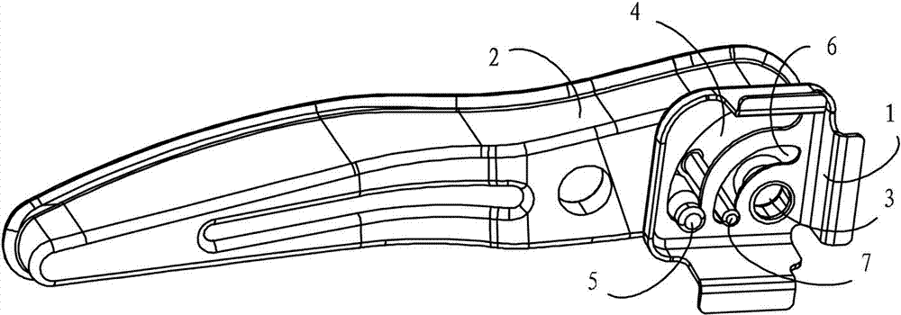
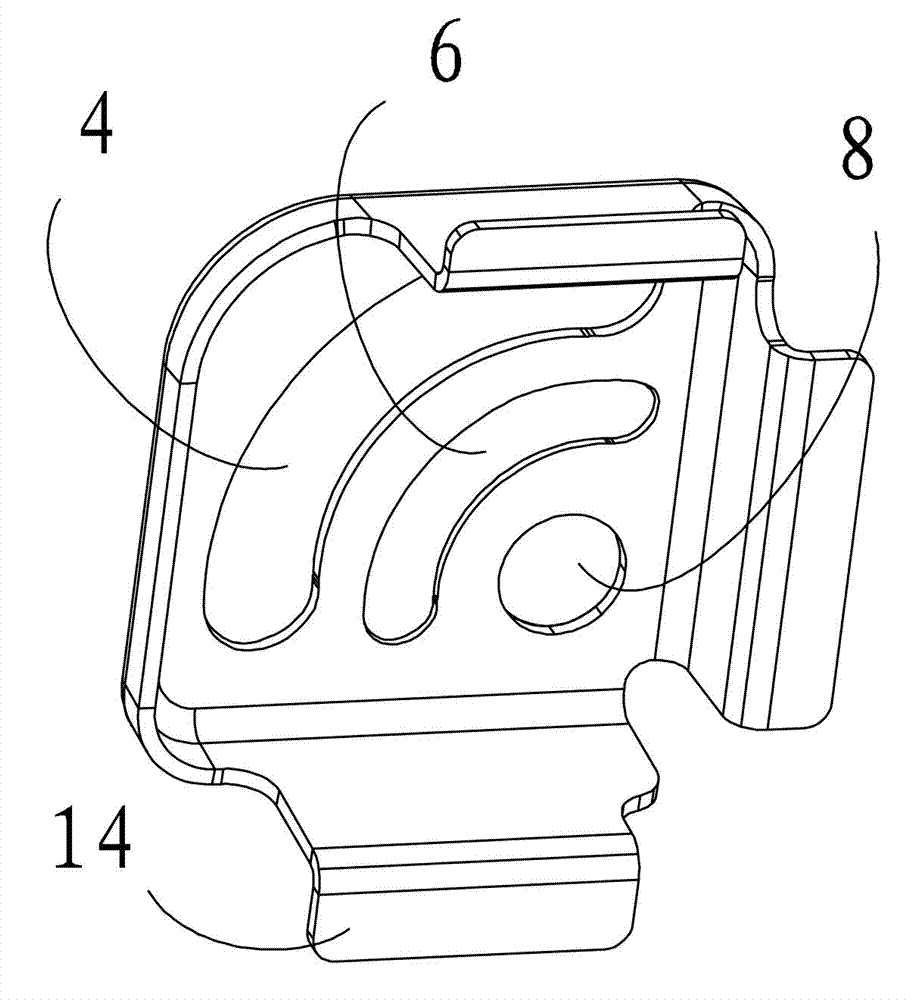
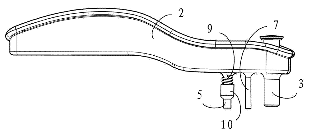
[0027] This embodiment relates to a seat armrest bracket structure, which consists of Figure 1 to Figure 3 As shown, it includes a mounting bracket 1 that is fixedly connected to the seat frame not shown in the figure, and is rotatably connected to the mounting bracket through a connecting shaft 3 arranged at one end thereof and a shaft mounting hole 8 on the mounting bracket 1. The handrail 2 on 1 is provided with the circular arc groove 4 and the second circular arc groove 6 arranged at intervals with the rotation center of the handrail 2 as the center of the circle on the mounting bracket 1, and the circular arc groove 4 inserted into the handrail 2 is respectively arranged on the armrest 2. and the second guide post 5 and the second guide post 7 sliding along the arc slot 4 and the second arc slot 6 when the handrail 2 rotates around its center of rotation. An elastic support mechanism is also provided on the side of the mounting bracket 1 facing the armrest 2 on the guid...

Embodiment 2

[0034] This embodiment relates to a seat armrest support structure, which has substantially the same structure as the seat armrest support structure in Embodiment 1, the difference is that Figure 8 As shown in , in this embodiment, the elastic support mechanism is arranged on the guide post 5 on the side of the mounting bracket 1 facing away from the handrail 2. At this time, in order to reduce the structural length of the guide post 5, the shaft of the support sleeve 10 can be The length is slightly shortened, and a support nut 16 is installed at the end of the guide post 5, and a second spring 17 is arranged between the support nut 16 and the support sleeve 10. After the armrest 2 is connected to the mounting bracket 1, it passes through the second The installation pretightening force of the two springs 17 pushes the support sleeve 10 so that the tapered end 13 of the support sleeve 10 is embedded in the arc groove 4 . In this embodiment, the movement process of the support...

Embodiment 3

[0036] This embodiment relates to a seat armrest support structure, which has substantially the same structure as the seat armrest support structure in Embodiment 1, the difference is that Figure 9 As shown in , it is provided with elastic supporting mechanisms on both sides of the mounting bracket 1 on the guide post 5 . A support nut 16 is installed at the end of the guide post 5 located at the side of the mounting bracket 1 facing away from the handrail 2, and between the support nut 16 and the mounting bracket 1 is a support sleeve 10 sleeved on the side of the guide post 5, for Reduce the structural length of the guide post 5, the axial length of the support sleeve 10 on this side is also slightly shortened, and a second spring 17 is also arranged between the support nut 16 and the support sleeve 10 on this side, and is connected to the armrest 2. After being installed on the bracket 1, under the promotion of the installation pre-tightening force of the first spring 9 an...


PUM


Abstract

The invention relates to a seat armrest support structure. The seat armrest support structure comprises a mounting bracket fixedly connected to a seat framework and an armrest connected to the mounting bracket in a rotating mode. The mounting bracket is provided with a circular arc groove and a second circular arc groove, wherein the rotation center of the armrest serves as the center of the circular arc groove and the center of the second circular arc groove; a guide pillar and a second guide pillar are arranged on the armrest, wherein the guide pillar and the second guide pillar are inserted into the circular arc groove and the second circular arc groove respectively and slide along the circular arc groove and the second circular arc groove respectively when the armrest is rotated around the center; the guide pillar is further provided with an elastic supporting mechanism, wherein the elastic supporting mechanism enables the guide pillar and the second guide pillar to make contact with the bottom of the circular arc groove and the bottom of the second circular arc groove respectively so that double-point support can be provided for the armrest when the armrest bears downward pressing force which is larger than or equal to basic downward pressing force. According to the seat armrest support structure, the armrest can be provided with extra support when a seat armrest bears quite large pressing force, it is guaranteed that the armrest is stably supported, and a damage problem is prevented; meanwhile, a passenger can be reminded when the armrest bears quite large acting force, and therefore it is guaranteed that the seat armrest can be used safely.

Description

technical field [0001] The invention relates to a component structure for an automobile seat, in particular to a seat armrest bracket structure. Background technique [0002] In passenger cars, especially passenger cars, most of the seats are provided with rotatable armrests on the outside of the seats. The armrests can be used to block and protect the passengers in the seats, so as to prevent the passengers from getting out of the seats when the car turns at high speed or when an accident occurs. It can provide further safety protection for passengers on the basis of seat belts, and at the same time, the armrest can also provide a hand rest support function for passengers after sitting for a long time, thereby increasing the comfort of the seat. [0003] In the current car seat armrest design, most of them adopt the flip-up and retractable mode that is installed on the side wall of the seat. Just at the side end of the backrest of the chair. And in order to increase the f...

Claims


Application Information

Patent Timeline
IPC IPC(8): B60N2/46B60N2/75
Inventor 董义梁雪娇安胜伟王柳刘庆松郝艳芳赵伟璞董志强孙永利
Owner GREAT WALL MOTOR CO LTD
Why Eureka
Try Eureka