Roller adjustable frame structure of carding machine

A rack structure, adjustable technology, applied in fiber processing, deburring devices, textiles and papermaking, etc., can solve problems such as falling on the rack, unsafe hidden dangers, unfavorable adjustments, etc., to reduce installation and improve carding Efficiency and shortening of working time

Active Publication Date: 2016-01-20
JIANGSU YINGYANG NONWOVEN MASCH CO LTD
View PDF13 Cites 3 Cited by
  • Summary
  • Abstract
  • Description
  • Claims
  • Application Information

AI Technical Summary

Problems solved by technology

[0006] In the prior art, fixing the wallboard directly to the frame can meet the working requirements of the carding machine, that is, it will not affect the normal operation of the carding machine, but it is not conducive to the adjustment during installation and the adjustment during maintenance. For example, when the fixing holes of the wallboard on the wallboard do not correspond to the fixing holes on the rack, it needs to be adjusted. During the adjustment, the installer usually holds a crowbar or similar tools to force the wallboard to Relocation on the rack
Therefore, on the one hand, the intensity of the installation work of the installation workers is increased, and on the other hand, it is accompanied by hidden dangers, because once the operation is wrong, the wallboard will fall on the frame, causing an accident. Take the adjustment during maintenance as an example. During card cylinder maintenance, e.g. when changing the card clothing (also called card cover) on the main card cylinder, it is necessary to orient the pre-card cylinder and / or the comb cylinder In order to avoid interference with the maintenance of the main carding roller, the maintenance staff will also use tools such as crowbars to move the wall panels used to support the pre-carding rollers together with the pre-carding rollers. Move on the frame (the wall panels used to support the combing rollers are the same as the combing rollers), after the maintenance of the main carding rollers is completed, the wallboards used to support the pre-combing rollers Resetting of wall panels together with pre-carding rollers (same example for wall panels supporting combing rollers)
It can be seen that the inspection and maintenance not only have the shortcomings in the aforementioned installation process, but also affect the efficiency of maintenance operations, prolong the downtime of the carding machine, and then affect the working efficiency of the carding machine
[0007] Undoubtedly, if the wall panels can slide relative to the frame, then the aforementioned problems can be eliminated, but there is no corresponding technical suggestion in the patents and non-patent literatures published so far

Method used


Image

  • Roller adjustable frame structure of carding machine
  • Roller adjustable frame structure of carding machine

Examples


Embodiment

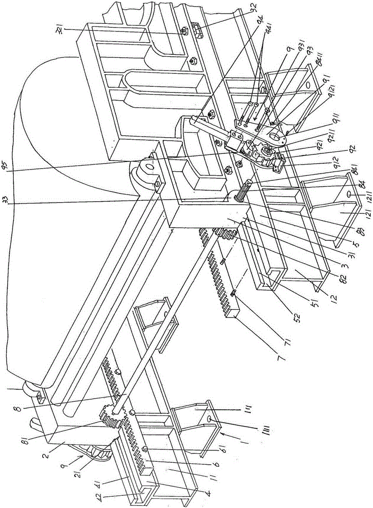
[0025] See figure 1 , a frame 1 is given, and the frame 1 includes a left bottom beam 11 and a right bottom beam 12, that is to say, the frame 1 is composed of left and right bottom beams 11, 12, and the left and right bottom beams The beams 11, 12 are kept parallel to each other in the length direction. When in use, the left bottom beam 11 and the right bottom beam 12 are supported on the floor of the place of use.

[0026] It can be seen from the schematic diagram of the figure that the cross-sectional shapes of the left bottom beam 11 and the right bottom beam 12 are both I-shaped, that is, I-shaped steel is used as the left bottom beam 11 and the right bottom beam 12. figure 1 In the middle, a group of left bottom beam supporting feet 111 and a group of right bottom beam supporting feet 121 are shown, and a group of left bottom beam supporting feet 111 are arranged in a spaced state along the length direction of the left bottom beam 11, and are connected with the left botto...


PUM


Abstract

The invention provides a roller-adjusting machine frame structure for a carding machine and belongs to the technical field of non-textile machines. The roller-adjusting machine frame structure comprises a machine frame body comprising a left bottom beam and a right bottom beam. A left roller bearing wallboard and a right roller bearing wallboard are arranged on the left bottom beam and the right bottom beam respectively. The roller-adjusting machine frame structure is characterized by further comprising a left bottom beam guide rail and a right bottom beam guide rail. The left bottom beam guide rail and the right bottom beam guide rail are fixed to the top of the left bottom beam and the top of the right bottom beam respectively. A left rack and a right rack are fixed to one side of the left bottom beam and one side of the right bottom beam in the length direction and correspond to each other. A gear shaft is supported on the left roller bearing wallboard. The right end of the gear shaft is supported on the right roller bearing wallboard. A left gear is fixed to the left end of the gear shaft. The left gear is meshed with the left rack. A right gear is fixed to the right end of the gear shaft and meshed with the right rack. The left end of the gear shaft extends to the left side of the left roller bearing wallboard and is provided with a gear shaft manual operating mechanism, and the right end of the gear shaft extends to the right side of the right roller bearing plate and is provided with a gear shaft manual operating mechanism. The installation and operation intensity is reduced, the operating time is shortened, the safety is guaranteed, the standby time for the carding machine to enter the working state is shortened, and the cotton carding efficiency is improved.

Description

technical field [0001] The invention belongs to the technical field of non-woven machinery, and in particular relates to an adjustable roller frame structure of a carding machine. Background technique [0002] The aforementioned rollers are the general term for the main carding rollers, pre-carding rollers and combed cotton rollers of the carding machine. [0003] The non-woven fibers are sequentially opened by an opener, carded by a carding machine, laid by a web-laying machine, and needle-punched by a needle-punching machine (or spunlace by a spunlace machine) to obtain a non-woven product. It can be seen that the carding machine is an indispensable part of the complete non-woven product production line. Its function is to comb the fibers loosened by the opener and transported by the conveyor curtain into a fluffy state for the subsequent web-laying machine. Lay the cotton net to the desired thickness. [0004] Technical information about carding machines can be found in...

Claims


Application Information

Patent Timeline
Patent Type & Authority Patents(China)
IPC IPC(8): D01G15/32D01G15/28
Inventor 范立元
Owner JIANGSU YINGYANG NONWOVEN MASCH CO LTD
Why Eureka
Try Eureka