
Fastening device for detector means

A fastening device and detector technology, applied in the direction of measuring devices, measuring instrument components, instruments, etc., can solve the problems of time-consuming fastening components, scrapping, etc., and achieve the effect of easy assembly

Inactive Publication Date: 2014-07-09
SCANIA CV AB
View PDF6 Cites 0 Cited by
  • Summary
  • Abstract
  • Description
  • Claims
  • Application Information

AI Technical Summary

Problems solved by technology

In the case of fitting a fastening element / fastening device suitable for a particular front window to a different front window for which the fastening element / fastening device is not suitable, the fastening element / fastening device must be removed or replaced, which is Time-consuming and means that the removed fastening elements have to be scrapped

Method used


Image

  • Fastening device for detector means
  • Fastening device for detector means
  • Fastening device for detector means

Examples


Embodiment Construction

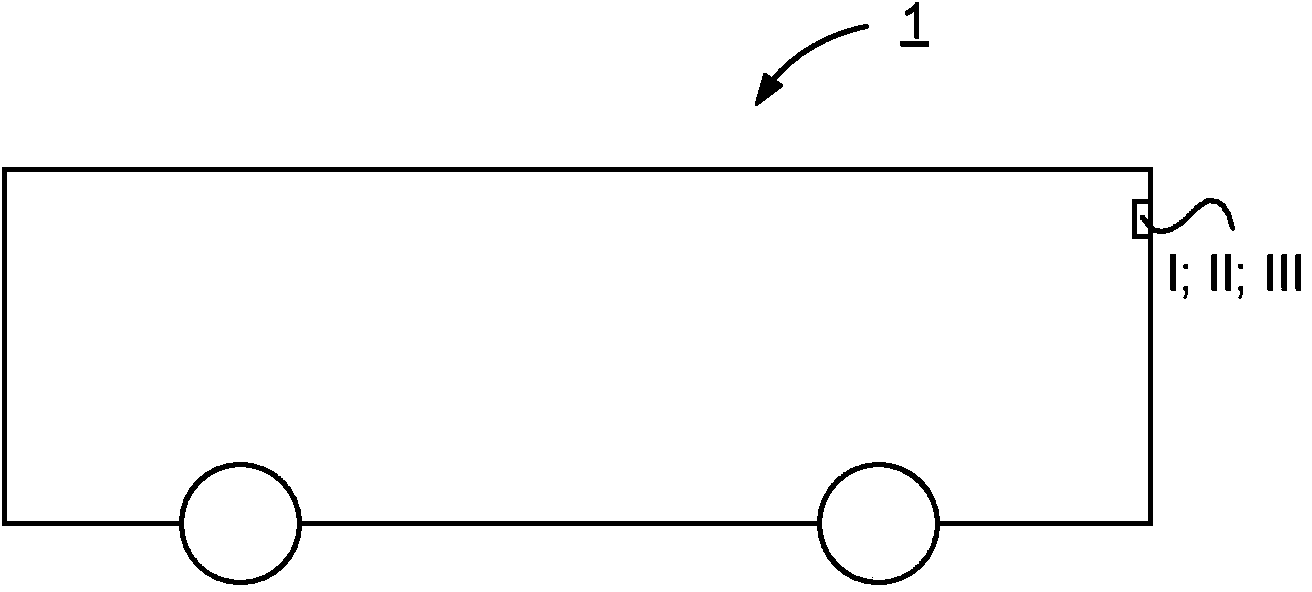
[0042] figure 1A side view of a vehicle 1 is depicted. The illustrated vehicle is a heavy vehicle in the form of a bus. The vehicle may alternatively be a truck or a car. The vehicle is equipped with a fastening device I; II; III for a detector component according to the invention.

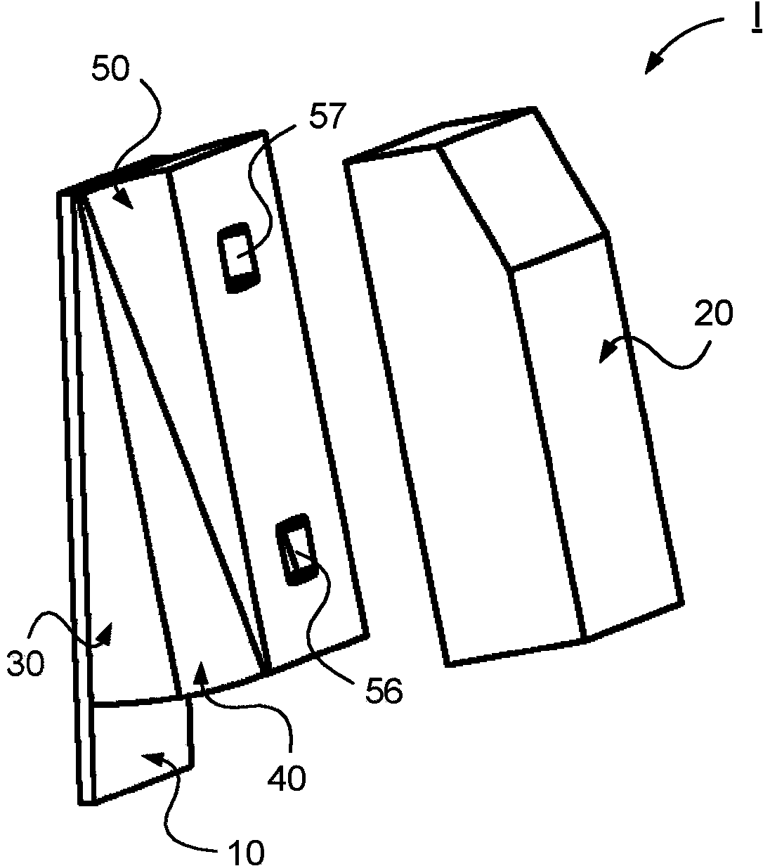
[0043] figure 2 is a schematic perspective view of a fastening device 1 for a detector member such as a camera in an assembled state according to an embodiment of the invention, Figure 3a yes figure 2 Perspective view of fastening device I in partially assembled, Figure 3b yes figure 2 The top view of each part of fastening device I in, Figure 4 yes figure 2 The perspective view of each part of the fastening device I in the unassembled state.

[0044] The fastening device 1 for supporting the detector member comprises a fastening element 10 for applying the fastening device. The fastening element 10 is suitable for fastening to a fastening surface W. As shown in FIG. In a varian...


PUM


Abstract

The invention relates to a fastening device (I; II; III) for support of detector means (20; 120; 220) comprising a fastening element (10; 1 10; 210) for applying the fastening device (I; II; III), comprising a fastening interface (15; 1 15; 215) on the fastening element (10; 1 10; 210) via which said detector means is intended to be supported via at least one fastening interface (24;34, 44, 54; 124, 134; 224, 234, 244) which corresponds to that of the fastening element (10; 1 10; 210), by means of the fastening element (10; 1 10). The invention relates also to a motor vehicle.

Description

technical field [0001] The invention relates to a fastening device for detector components according to the preamble of claim 1 . The invention also relates to a motor vehicle. Background technique [0002] Detectors are widely used today, for example in motor vehicles, for various types of monitoring. It is desirable to securely fasten such detectors. In certain cases, the detector needs to be adjustable ex ante and / or ex post so that the position / orientation of the detector can be adjusted to suit the particular location of the detector. For example, there are various current applications in which detectors in the form of cameras are fitted in vehicle front windows, for example in order to detect and identify objects such as unprotected road users in the vehicle's path. [0003] Such a camera is preferably fitted inside the front window of the vehicle to protect the camera from external influences. The problem with having the camera on the inside is that the vehicle fr...

Claims


Application Information

Patent Timeline
Patent Type & Authority Applications(China)
IPC IPC(8): B60R11/04G01D11/30
CPCB60R11/04G01D11/30B60R2011/0026H04N23/50
Inventor A·奥尔森K·杜罗斯S·约恩松S·卡尔松
Owner SCANIA CV AB
Learn More